1. General Introduction
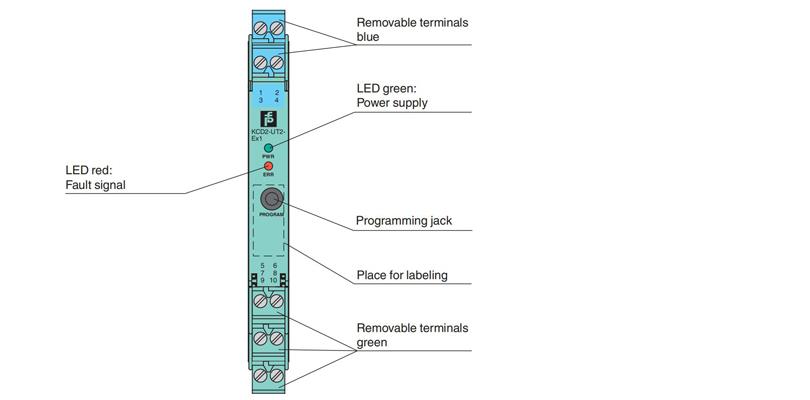
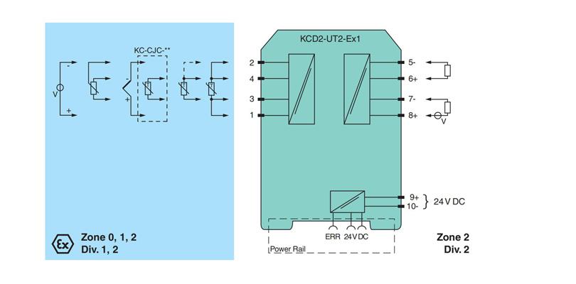
The removable terminal block KC-CJC-** is available for thermocouples when internal cold junction compensation is desired. A fault is indicated by an LED and by user-configured fault indication outputs. If the device is operated via Power Rail, additionally a collective error message is available. The device is easily configured by the use of the PACTware configuration software.For additional information, refer to the manual and www.pepperl-fuchs.com.
2. General Specification for KFD2-GU-1
Model | KFD2-GU-1 |
General specifications | |
Signal type | Analog input |
Functional safety related parameters | |
Safety Integrity Level (SIL | SIL 2 |
Supply | |
Connection | terminals 9+, 10- or power feed module/Power Rail |
Rated voltage Ur | 19 ... 30 V DC |
Ripple | within the supply tolerance |
Power dissipation/power consumption | ≤ 0.98 W / 0.98 W |
Interface | |
Programming interface | programming socket |
Input | |
Connection side | field side |
Connection | terminals 1, 2, 3, 4 |
RTD | type Pt10, Pt50, Pt100, Pt500, Pt1000 (EN 60751: 1995) type Pt10GOST, Pt50GOST, Pt100GOST, Pt500GOST, Pt1000GOST (6651-94) type Cu10, Cu50, Cu100 (P50353-92) type Ni100 (DIN 43760) |
Measuring current | approx. 200 μA with RTD |
Types of measuring | 2-, 3-, 4-wire connection |
Lead resistance | ≤ 50 Ω per line |
Measurement loop monitoring | sensor breakage, sensor short-circuit |
Thermocouples | type B, E, J, K, N, R, S, T (IEC 584-1: 1995) type L (DIN 43710: 1985) type TXK, TXKH, TXA (P8.585-2001 |
Cold junction compensation | external and internal |
Measurement loop monitoring | sensor breakage |
Potentiometer | 0 ... 20 kΩ (2-wire connection), 0.8 ... 20 kΩ (3-wire connection) |
Voltage | selectable within the range -100 ... 100 mV |
Input resistance | ≥ 1 MΩ (-100 ... 100 mV) |
Output | |
Connection side | control side |
Connection | terminal 5: source (-), terminal 6: source (+), terminal 7: sink(-), terminal 8: sink (+) |
Output | Analog current output |
Current range | 0 ... 20 mA or 4 ... 20 mA |
Fault signal | downscale 0 or 2 mA, upscale 21.5 mA (acc. NAMUR NE43) |
Source | load 0 ... 550 Ω open-circuit voltage ≤ 18 V |
Sink | Voltage across terminals 5 ... 30 V. If the current is supplied from a source > 16.5 V, series resistance of ≥ (V - 16.5)/0.0215 Ω is needed, where V is the source voltage. The maximum value of the resistance is (V - 5)/0.0215 Ω. |
Transfer characteristics | |
Deviation | |
After calibration | Pt100: ± (0.06 % of measurement value in K + 0.1 % of span + 0.1 K (4-wire connection)) thermocouple: ± (0.05 % of measurement value in °C + 0.1 % of span + 1.5 K (1.7 K for types R and S)) this includes ± 1.3 K error of the cold junction compensation mV: ± (50 μV + 0.1 % of span) potentiometer: ± (0.05 % of full scale + 0.1 % of span, (excludes errors due to lead resistance)) |
Influence of ambient temperature | deviation of CJC included: Pt100: ± (0.0015 % of measurement value in K + 0.006 % of span)/K ΔTamb*) thermocouple: ± (0.02 K + 0.005 % of measurement value in °C + 0.006 % of span)/K ΔTamb*) mV: ± (0.01 % of measurement value + 0.006 % of span)/K ΔTamb*) potentiometer: ± 0.006 % of span/K ΔTamb*) *) ΔTamb = ambient temperature change referenced to 23 °C (296 K) |
Influence of supply voltage | < 0.01 % of span |
Influence of load | ≤ 0.001 % of output value per 100 Ω |
Reaction time | worst case value (sensor breakage and/or sensor short circuit detection enabled) mV: 1 s, thermocouples with CJC: 1.1 s, thermocouples with fixed reference temperature: 1.1 s, 3- or 4-wire RTD: 920 ms, 2-wire RTD: 800 ms, Potentiometer: 2.05 s |
Galvanic isolation | |
Output/supply, programming input | functional insulation, rated insulation voltage 50 V AC There is no electrical isolation between the programming input and the supply. The programming cable provides galvanic isolation so that ground loops are avoided |
Indicators/settings | |
Display elements | LEDs |
Configuration | via PACTware |
Labeling | space for labeling at the front |
Directive conformity | |
Electromagnetic compatibility | |
Directive 2014/30/EU | EN 61326-1:2013 (industrial locations) |
Conformity | |
Electromagnetic compatibility | NE 21:2011 |
Degree of protection | IEC 60529:2001 |
Protection against electrical shock | UL 61010-1:2004 |
Ambient conditions | |
Ambient temperature | -20 ... 60 °C (-4 ... 140 °F) |
3. Connection
4. Assembly