1. General introduction
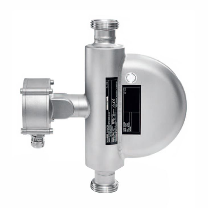
Hygienic Coriolis mass flow meter specifically designed and certified for food & beverage, biotechnology and pharmaceutical utility applications, typical line sizes: DN15, DN25, DN40, DN50, DN65, DN80, 1/2”, 1”, 1 1/2”, 2” and Maximum mass flow up to 80 t/h. This series is the appropriate answer to the daily constraints of hygienic processes ensuring continuous product quality and minimizing losses, this is made easy by the provided multi-variable measurement and various dedicated features.
2. Measuring range limits
Meter size | Normal Mass Flow | Maximum mass flow | Normal Volume flow | Max Volume flow | Normal Temperature | Max. Temperature | Density |
Hygienic 25 | 1.6 t/h | 2.3 t/h | 1.6m3/h | 2.3 m3/h | -50 to140℃ | -70 to 140℃ | 0 to 5 kg/l |
Hygienic 40 | 4.7 t/h | 7 t/h | 4.7 m3/h | 7 m3/h | |||
Hygienic 50 | 20 t/h | 29 t/h | 20 m3/h | 29 m3/h | |||
Hygienic 80 | 51 t/h | 76 t/h | 51 m3/h | 76 m3/h |
3. Accuracy of liquids measurement
Measured quantity | Accuracy for transmitters | ||
Essential | Ultimate | ||
Mass flow | Accuracy | 0.15 % of measured value | 0.1 % of measured value |
Repeatability | 0.08 % of measured value | 0.05 % of measured value | |
Volume flow | Accuracy | 0.43 % of measured value | 0.12 % of measured value |
Repeatability | 0.22 % of measured value | 0.06 % of measured value | |
Density | Accuracy | 4 g/l (0.25 lb/ft³) | 0.5 g/l (0.03 lb/ft³) |
Repeatability | 2 g/l (0.13 lb/ft³) | 0.3 g/l (0.02 lb/ft³) | |
Temperature | Accuracy | 1℃ (1.8℉) | 1℃ (1.8℉) |
4. Accuracy of gas measurement
Measured quantity | Accuracy for transmitters | ||
Essential | Ultimate | ||
Mass flow | Accuracy | 0.75 % of measured value | 0.5 % of measured value |
Repeatability | 0.6 % of measured value | 0.4 % of measured value | |
Volume flow | Accuracy | 0.75 % of measured value | 0.5 % of measured value |
Repeatability | 0.6 % of measured value | 0.4 % of measured value | |
Temperature | Accuracy | 1℃ (1.8℉) | 1℃ (1.8℉) |
5. Model selection of Hygienic 25
Main Code | Suffix Codes | Description | |||||||||||||
RC | Always RC | ||||||||||||||
Transmitter | E | Essential (base function) | |||||||||||||
U | Ultimate (high function) | ||||||||||||||
Sensor | H | Hygienic | |||||||||||||
Meter size | 25 | Nominal mass flow : 1.6 t/h (59 lb/min), Maximum mass flow: 2.3 t/h (85 lb/min) | |||||||||||||
Material of wetted parts | S | Stainless steel 1.4404/316L | |||||||||||||
Process connection size | 25 | DN25, 1" | |||||||||||||
40 | DN40, 1½" | ||||||||||||||
Process connection type | HS2 | Threaded connection according to DIN 11851 | |||||||||||||
HS4 | Clamp process connection according to DIN 32676 series A | ||||||||||||||
HS8 | Clamp process connection according to DIN 32676 series C (Tri-Clamp) | ||||||||||||||
Sensor housing 0material | 0 | Stainless steel 1.4301/304, 1.4404/316L | |||||||||||||
Process fluid temperature range | 0 | Standard integrate: -50 to 150℃ (-58 to 302℉), remote type: -70 to 200 °C (-94 – 392 °F) | |||||||||||||
Mass flow and density accuracy | E7 | Liquid: 0.2 % maximum mass flow deviation, 4 g/l density deviation | |||||||||||||
D7 | Liquid: 0.15 % maximum mass flow deviation, 4 g/l density deviation | ||||||||||||||
C7 | Liquid: 0.1 % maximum mass flow deviation, 4 g/l density deviation | ||||||||||||||
C3 | Liquid: 0.1 % maximum mass flow deviation, 1 g/l density deviation | ||||||||||||||
C2 | Liquid: 0.1 % maximum mass flow deviation, 0.5 g/l density deviation | ||||||||||||||
70 | Gas: 0.75% maximum mass flow deviation | ||||||||||||||
50 | Gas: 0.5% maximum mass flow deviation | ||||||||||||||
Design and housing | 0 | Integral type with "urethane-cured polyester powder coating" coated aluminum transmitter housing | |||||||||||||
2 | Integral type with "corrosion protection coating" coated aluminum transmitter housing | ||||||||||||||
A | Remote type with "urethane-cured polyester powder coating" coated aluminum transmitter housing and standard neck sensor | ||||||||||||||
E | Remote type with "corrosion protection coating" coated aluminum transmitter housing and standard neck sensor | ||||||||||||||
J | Remote type stainless steel transmitter and standard neck sensor | ||||||||||||||
Ex approval | NN00 | None | |||||||||||||
KF21 | ATEX, explosion group IIC and IIIC | ||||||||||||||
KF22 | ATEX, explosion group IIB and IIIC | ||||||||||||||
SF21 | IECEx, explosion group IIC and IIIC | ||||||||||||||
SF22 | IECEx, explosion group IIB and IIIC | ||||||||||||||
GF21 | EAC Ex, explosion group IIC and IIIC | ||||||||||||||
GF22 | EAC Ex, explosion group IIB and IIIC | ||||||||||||||
FF11 | FM, groups A, B, C, D, E, F, G | ||||||||||||||
FF12 | FM, groups C, D, E, F, G | ||||||||||||||
UF21 | INMETRO, explosion group IIC and IIIC | ||||||||||||||
UF22 | INMETRO, explosion group IIB and IIIC | ||||||||||||||
NF21 | NEPSI, explosion group IIC and IIIC | ||||||||||||||
NF22 | NEPSI, explosion group IIB and IIIC | ||||||||||||||
PF21 | Korea Ex, explosion group IIC and IIIC | ||||||||||||||
PF22 | Korea Ex, explosion group IIB and IIIC | ||||||||||||||
Cable entries | 2 | ANSI ½" NPT | |||||||||||||
4 | ISO M20x1.5 | ||||||||||||||
Communication type and I/O | JA | active current output HART,1 passive pulse or status output | |||||||||||||
JB | 2 active current outputs one with HART,2 passive pulse or status outputs | ||||||||||||||
JC | 2 active current outputs one with HART,1 passive pulse or status output,1 voltage-free status input | ||||||||||||||
JD | 1 active current output HART,2 passive pulse or status outputs,1 passive status output | ||||||||||||||
JE | 1 active current output HART,2 passive pulse or status outputs,1 voltage-free status input | ||||||||||||||
JF | 1 active current output HART,1 passive pulse or status output,1 active pulse or status output with pull-up resistor,1 voltage-free status input | ||||||||||||||
JG | 1 active current output HART,1 passive pulse or status output,1 active pulse or status output,1 voltage-free status input | ||||||||||||||
JH | 1 active current output HART,1 passive pulse or status output,1 passive current output,1 active current input | ||||||||||||||
JJ | 1 active current output HART,2 passive pulse or status outputs,1 active current input | ||||||||||||||
JK | 1 active current output HART,1 passive pulse or status output,1 voltage-free status input,1 active current input | ||||||||||||||
JL | 1 active current output HART,1 passive pulse or status output,1 passive current output,1 passive current input | ||||||||||||||
JM | 1 active current output HART, 2 passive pulse or status outputs,1 passive current input | ||||||||||||||
JN | 1 active current output HART,1 passive pulse or status output,1 voltage-free status input,1 passive current input | ||||||||||||||
JP | 2 passive current outputs one with HART,1 passive pulse or status output | ||||||||||||||
JQ | 2 passive current outputs one with HART,2 passive pulse or status outputs | ||||||||||||||
JR | 2 passive current outputs one with HART,1 passive NAMUR pulse or status output | ||||||||||||||
JS | 2 passive current outputs one with HART,2 passive NAMUR pulse or status outputs | ||||||||||||||
M0 | Modbus output,1 passive pulse or status output | ||||||||||||||
M2 | Modbus output,1 passive pulse or status output,1 active current input | ||||||||||||||
M3 | Modbus output, 2 passive pulse or status outputs | ||||||||||||||
M4 | Modbus output,1 passive pulse or status output, 1 active pulse or status output | ||||||||||||||
M5 | Modbus output, 1 passive pulse or status output, 1 active pulse or status output with pull-up resistor | ||||||||||||||
M6 | Modbus output,1 passive pulse or status output, 1 active current output | ||||||||||||||
M7 | Modbus output, 1 passive pulse or status output, 1 passive current input | ||||||||||||||
Display | 0 | No display | |||||||||||||
1 | With display | ||||||||||||||
Optional codes | /Optional codes | ||||||||||||||
6. Model selection of Hygienic 40
Main Code | Suffix Codes | Description | |||||||||||||
RC | Always RC | ||||||||||||||
Transmitter | E | Essential (base function) | |||||||||||||
U | Ultimate (high function) | ||||||||||||||
Sensor | H | Hygienic | |||||||||||||
Meter size | 40 | Nominal mass flow : 4.7 t/h (170 lb/min), Maximum mass flow: 7 t/h (260 lb/min) | |||||||||||||
Material of wetted parts | S | Stainless steel 1.4404/316L | |||||||||||||
Process connection size | 25 | DN25, 1" | |||||||||||||
40 | DN40, 1½" | ||||||||||||||
Process connection type | HS2 | Threaded connection according to DIN 11851 | |||||||||||||
HS4 | Clamp process connection according to DIN 32676 series A | ||||||||||||||
HS8 | Clamp process connection according to DIN 32676 series C (Tri-Clamp) | ||||||||||||||
Sensor housing 0material | 0 | Stainless steel 1.4301/304, 1.4404/316L | |||||||||||||
Process fluid temperature range | 0 | Standard integrate: -50 to 150℃ (-58 to 302℉), remote type: -70 to 200 °C (-94 – 392 °F) | |||||||||||||
Mass flow and density accuracy | E7 | Liquid: 0.2 % maximum mass flow deviation, 4 g/l density deviation | |||||||||||||
D7 | Liquid: 0.15 % maximum mass flow deviation, 4 g/l density deviation | ||||||||||||||
C7 | Liquid: 0.1 % maximum mass flow deviation, 4 g/l density deviation | ||||||||||||||
C3 | Liquid: 0.1 % maximum mass flow deviation, 1 g/l density deviation | ||||||||||||||
C2 | Liquid: 0.1 % maximum mass flow deviation, 0.5 g/l density deviation | ||||||||||||||
70 | Gas: 0.75% maximum mass flow deviation | ||||||||||||||
50 | Gas: 0.5% maximum mass flow deviation | ||||||||||||||
Design and housing | 0 | Integral type with "urethane-cured polyester powder coating" coated aluminum transmitter housing | |||||||||||||
2 | Integral type with "corrosion protection coating" coated aluminum transmitter housing | ||||||||||||||
A | Remote type with "urethane-cured polyester powder coating" coated aluminum transmitter housing and standard neck sensor | ||||||||||||||
E | Remote type with "corrosion protection coating" coated aluminum transmitter housing and standard neck sensor | ||||||||||||||
J | Remote type stainless steel transmitter and standard neck sensor | ||||||||||||||
Ex approval | NN00 | None | |||||||||||||
KF21 | ATEX, explosion group IIC and IIIC | ||||||||||||||
KF22 | ATEX, explosion group IIB and IIIC | ||||||||||||||
SF21 | IECEx, explosion group IIC and IIIC | ||||||||||||||
SF22 | IECEx, explosion group IIB and IIIC | ||||||||||||||
GF21 | EAC Ex, explosion group IIC and IIIC | ||||||||||||||
GF22 | EAC Ex, explosion group IIB and IIIC | ||||||||||||||
FF11 | FM, groups A, B, C, D, E, F, G | ||||||||||||||
FF12 | FM, groups C, D, E, F, G | ||||||||||||||
UF21 | INMETRO, explosion group IIC and IIIC | ||||||||||||||
UF22 | INMETRO, explosion group IIB and IIIC | ||||||||||||||
NF21 | NEPSI, explosion group IIC and IIIC | ||||||||||||||
NF22 | NEPSI, explosion group IIB and IIIC | ||||||||||||||
PF21 | Korea Ex, explosion group IIC and IIIC | ||||||||||||||
PF22 | Korea Ex, explosion group IIB and IIIC | ||||||||||||||
Cable entries | 2 | ANSI ½" NPT | |||||||||||||
4 | ISO M20x1.5 | ||||||||||||||
Communication type and I/O | JA | active current output HART,1 passive pulse or status output | |||||||||||||
JB | 2 active current outputs one with HART,2 passive pulse or status outputs | ||||||||||||||
JC | 2 active current outputs one with HART,1 passive pulse or status output,1 voltage-free status input | ||||||||||||||
JD | 1 active current output HART,2 passive pulse or status outputs,1 passive status output | ||||||||||||||
JE | 1 active current output HART,2 passive pulse or status outputs,1 voltage-free status input | ||||||||||||||
JF | 1 active current output HART,1 passive pulse or status output,1 active pulse or status output with pull-up resistor,1 voltage-free status input | ||||||||||||||
JG | 1 active current output HART,1 passive pulse or status output,1 active pulse or status output,1 voltage-free status input | ||||||||||||||
JH | 1 active current output HART,1 passive pulse or status output,1 passive current output,1 active current input | ||||||||||||||
JJ | 1 active current output HART,2 passive pulse or status outputs,1 active current input | ||||||||||||||
JK | 1 active current output HART,1 passive pulse or status output,1 voltage-free status input,1 active current input | ||||||||||||||
JL | 1 active current output HART,1 passive pulse or status output,1 passive current output,1 passive current input | ||||||||||||||
JM | 1 active current output HART, 2 passive pulse or status outputs,1 passive current input | ||||||||||||||
JN | 1 active current output HART,1 passive pulse or status output,1 voltage-free status input,1 passive current input | ||||||||||||||
JP | 2 passive current outputs one with HART,1 passive pulse or status output | ||||||||||||||
JQ | 2 passive current outputs one with HART,2 passive pulse or status outputs | ||||||||||||||
JR | 2 passive current outputs one with HART,1 passive NAMUR pulse or status output | ||||||||||||||
JS | 2 passive current outputs one with HART,2 passive NAMUR pulse or status outputs | ||||||||||||||
M0 | Modbus output,1 passive pulse or status output | ||||||||||||||
M2 | Modbus output,1 passive pulse or status output,1 active current input | ||||||||||||||
M3 | Modbus output, 2 passive pulse or status outputs | ||||||||||||||
M4 | Modbus output,1 passive pulse or status output, 1 active pulse or status output | ||||||||||||||
M5 | Modbus output, 1 passive pulse or status output, 1 active pulse or status output with pull-up resistor | ||||||||||||||
M6 | Modbus output,1 passive pulse or status output, 1 active current output | ||||||||||||||
M7 | Modbus output, 1 passive pulse or status output, 1 passive current input | ||||||||||||||
Display | 0 | No display | |||||||||||||
1 | With display | ||||||||||||||
Optional codes | /Optional codes | ||||||||||||||
7. Model selection of Hygienic 50
Main Code | Suffix Codes | Description | |||||||||||||
RC | Always RC | ||||||||||||||
Transmitter | E | Essential (base function) | |||||||||||||
U | Ultimate (high function) | ||||||||||||||
Sensor | H | Hygienic | |||||||||||||
Meter size | 50 | Nominal mass flow : 20 t/h (730 lb/min), Maximum mass flow: 29 t/h (1100 lb/min) | |||||||||||||
Material of wetted parts | S | Stainless steel 1.4404/316L | |||||||||||||
Process connection size | 25 | DN25, 1" | |||||||||||||
40 | DN40, 1½" | ||||||||||||||
Process connection type | HS2 | Threaded connection according to DIN 11851 | |||||||||||||
HS4 | Clamp process connection according to DIN 32676 series A | ||||||||||||||
HS8 | Clamp process connection according to DIN 32676 series C (Tri-Clamp) | ||||||||||||||
Sensor housing 0material | 0 | Stainless steel 1.4301/304, 1.4404/316L | |||||||||||||
Process fluid temperature range | 0 | Standard integrate: -50 to 150℃ (-58 to 302℉), remote type: -70 to 200 °C (-94 – 392 °F) | |||||||||||||
Mass flow and density accuracy | E7 | Liquid: 0.2 % maximum mass flow deviation, 4 g/l density deviation | |||||||||||||
D7 | Liquid: 0.15 % maximum mass flow deviation, 4 g/l density deviation | ||||||||||||||
C7 | Liquid: 0.1 % maximum mass flow deviation, 4 g/l density deviation | ||||||||||||||
C3 | Liquid: 0.1 % maximum mass flow deviation, 1 g/l density deviation | ||||||||||||||
C2 | Liquid: 0.1 % maximum mass flow deviation, 0.5 g/l density deviation | ||||||||||||||
70 | Gas: 0.75% maximum mass flow deviation | ||||||||||||||
50 | Gas: 0.5% maximum mass flow deviation | ||||||||||||||
Design and housing | 0 | Integral type with "urethane-cured polyester powder coating" coated aluminum transmitter housing | |||||||||||||
2 | Integral type with "corrosion protection coating" coated aluminum transmitter housing | ||||||||||||||
A | Remote type with "urethane-cured polyester powder coating" coated aluminum transmitter housing and standard neck sensor | ||||||||||||||
E | Remote type with "corrosion protection coating" coated aluminum transmitter housing and standard neck sensor | ||||||||||||||
J | Remote type stainless steel transmitter and standard neck sensor | ||||||||||||||
Ex approval | NN00 | None | |||||||||||||
KF21 | ATEX, explosion group IIC and IIIC | ||||||||||||||
KF22 | ATEX, explosion group IIB and IIIC | ||||||||||||||
SF21 | IECEx, explosion group IIC and IIIC | ||||||||||||||
SF22 | IECEx, explosion group IIB and IIIC | ||||||||||||||
GF21 | EAC Ex, explosion group IIC and IIIC | ||||||||||||||
GF22 | EAC Ex, explosion group IIB and IIIC | ||||||||||||||
FF11 | FM, groups A, B, C, D, E, F, G | ||||||||||||||
FF12 | FM, groups C, D, E, F, G | ||||||||||||||
UF21 | INMETRO, explosion group IIC and IIIC | ||||||||||||||
UF22 | INMETRO, explosion group IIB and IIIC | ||||||||||||||
NF21 | NEPSI, explosion group IIC and IIIC | ||||||||||||||
NF22 | NEPSI, explosion group IIB and IIIC | ||||||||||||||
PF21 | Korea Ex, explosion group IIC and IIIC | ||||||||||||||
PF22 | Korea Ex, explosion group IIB and IIIC | ||||||||||||||
Cable entries | 2 | ANSI ½" NPT | |||||||||||||
4 | ISO M20x1.5 | ||||||||||||||
Communication type and I/O | JA | active current output HART,1 passive pulse or status output | |||||||||||||
JB | 2 active current outputs one with HART,2 passive pulse or status outputs | ||||||||||||||
JC | 2 active current outputs one with HART,1 passive pulse or status output,1 voltage-free status input | ||||||||||||||
JD | 1 active current output HART,2 passive pulse or status outputs,1 passive status output | ||||||||||||||
JE | 1 active current output HART,2 passive pulse or status outputs,1 voltage-free status input | ||||||||||||||
JF | 1 active current output HART,1 passive pulse or status output,1 active pulse or status output with pull-up resistor,1 voltage-free status input | ||||||||||||||
JG | 1 active current output HART,1 passive pulse or status output,1 active pulse or status output,1 voltage-free status input | ||||||||||||||
JH | 1 active current output HART,1 passive pulse or status output,1 passive current output,1 active current input | ||||||||||||||
JJ | 1 active current output HART,2 passive pulse or status outputs,1 active current input | ||||||||||||||
JK | 1 active current output HART,1 passive pulse or status output,1 voltage-free status input,1 active current input | ||||||||||||||
JL | 1 active current output HART,1 passive pulse or status output,1 passive current output,1 passive current input | ||||||||||||||
JM | 1 active current output HART, 2 passive pulse or status outputs,1 passive current input | ||||||||||||||
JN | 1 active current output HART,1 passive pulse or status output,1 voltage-free status input,1 passive current input | ||||||||||||||
JP | 2 passive current outputs one with HART,1 passive pulse or status output | ||||||||||||||
JQ | 2 passive current outputs one with HART,2 passive pulse or status outputs | ||||||||||||||
JR | 2 passive current outputs one with HART,1 passive NAMUR pulse or status output | ||||||||||||||
JS | 2 passive current outputs one with HART,2 passive NAMUR pulse or status outputs | ||||||||||||||
M0 | Modbus output,1 passive pulse or status output | ||||||||||||||
M2 | Modbus output,1 passive pulse or status output,1 active current input | ||||||||||||||
M3 | Modbus output, 2 passive pulse or status outputs | ||||||||||||||
M4 | Modbus output,1 passive pulse or status output, 1 active pulse or status output | ||||||||||||||
M5 | Modbus output, 1 passive pulse or status output, 1 active pulse or status output with pull-up resistor | ||||||||||||||
M6 | Modbus output,1 passive pulse or status output, 1 active current output | ||||||||||||||
M7 | Modbus output, 1 passive pulse or status output, 1 passive current input | ||||||||||||||
Display | 0 | No display | |||||||||||||
1 | With display | ||||||||||||||
Optional codes | /Optional codes | ||||||||||||||
8. Model selection of Hygienic 80
Main Code | Suffix Codes | Description | |||||||||||||
RC | Always RC | ||||||||||||||
Transmitter | E | Essential (base function) | |||||||||||||
U | Ultimate (high function) | ||||||||||||||
Sensor | H | Hygienic | |||||||||||||
Meter size | 80 | Nominal mass flow : 51 t/h (1900 lb/min), Maximum mass flow: 76 t/h (2800 lb/min) | |||||||||||||
Material of wetted parts | S | Stainless steel 1.4404/316L | |||||||||||||
50 | DN50, 2" | ||||||||||||||
65 | DN65, 2-1/2" | ||||||||||||||
80 | DN80, 3" | ||||||||||||||
HS2 | Threaded connection according to DIN 11851 | ||||||||||||||
HS4 | Clamp process connection according to DIN 32676 series A | ||||||||||||||
HS8 | Clamp process connection according to DIN 32676 series C (Tri-Clamp) | ||||||||||||||
Sensor housing 0material | 0 | Stainless steel 1.4301/304, 1.4404/316L | |||||||||||||
Process fluid temperature range | 0 | Standard integrate: -50 to 150℃ (-58 to 302℉), remote type: -70 to 200 °C (-94 – 392 °F) | |||||||||||||
Mass flow and density accuracy | E7 | Liquid: 0.2 % maximum mass flow deviation, 4 g/l density deviation | |||||||||||||
D7 | Liquid: 0.15 % maximum mass flow deviation, 4 g/l density deviation | ||||||||||||||
C7 | Liquid: 0.1 % maximum mass flow deviation, 4 g/l density deviation | ||||||||||||||
C3 | Liquid: 0.1 % maximum mass flow deviation, 1 g/l density deviation | ||||||||||||||
C2 | Liquid: 0.1 % maximum mass flow deviation, 0.5 g/l density deviation | ||||||||||||||
70 | Gas: 0.75% maximum mass flow deviation | ||||||||||||||
50 | Gas: 0.5% maximum mass flow deviation | ||||||||||||||
Design and housing | 0 | Integral type with "urethane-cured polyester powder coating" coated aluminum transmitter housing | |||||||||||||
2 | Integral type with "corrosion protection coating" coated aluminum transmitter housing | ||||||||||||||
A | Remote type with "urethane-cured polyester powder coating" coated aluminum transmitter housing and standard neck sensor | ||||||||||||||
E | Remote type with "corrosion protection coating" coated aluminum transmitter housing and standard neck sensor | ||||||||||||||
J | Remote type stainless steel transmitter and standard neck sensor | ||||||||||||||
Ex approval | NN00 | None | |||||||||||||
KF21 | ATEX, explosion group IIC and IIIC | ||||||||||||||
KF22 | ATEX, explosion group IIB and IIIC | ||||||||||||||
SF21 | IECEx, explosion group IIC and IIIC | ||||||||||||||
SF22 | IECEx, explosion group IIB and IIIC | ||||||||||||||
GF21 | EAC Ex, explosion group IIC and IIIC | ||||||||||||||
GF22 | EAC Ex, explosion group IIB and IIIC | ||||||||||||||
FF11 | FM, groups A, B, C, D, E, F, G | ||||||||||||||
FF12 | FM, groups C, D, E, F, G | ||||||||||||||
UF21 | INMETRO, explosion group IIC and IIIC | ||||||||||||||
UF22 | INMETRO, explosion group IIB and IIIC | ||||||||||||||
NF21 | NEPSI, explosion group IIC and IIIC | ||||||||||||||
NF22 | NEPSI, explosion group IIB and IIIC | ||||||||||||||
PF21 | Korea Ex, explosion group IIC and IIIC | ||||||||||||||
PF22 | Korea Ex, explosion group IIB and IIIC | ||||||||||||||
Cable entries | 2 | ANSI ½" NPT | |||||||||||||
4 | ISO M20x1.5 | ||||||||||||||
Communication type and I/O | JA | active current output HART,1 passive pulse or status output | |||||||||||||
JB | 2 active current outputs one with HART,2 passive pulse or status outputs | ||||||||||||||
JC | 2 active current outputs one with HART,1 passive pulse or status output,1 voltage-free status input | ||||||||||||||
JD | 1 active current output HART,2 passive pulse or status outputs,1 passive status output | ||||||||||||||
JE | 1 active current output HART,2 passive pulse or status outputs,1 voltage-free status input | ||||||||||||||
JF | 1 active current output HART,1 passive pulse or status output,1 active pulse or status output with pull-up resistor,1 voltage-free status input | ||||||||||||||
JG | 1 active current output HART,1 passive pulse or status output,1 active pulse or status output,1 voltage-free status input | ||||||||||||||
JH | 1 active current output HART,1 passive pulse or status output,1 passive current output,1 active current input | ||||||||||||||
JJ | 1 active current output HART,2 passive pulse or status outputs,1 active current input | ||||||||||||||
JK | 1 active current output HART,1 passive pulse or status output,1 voltage-free status input,1 active current input | ||||||||||||||
JL | 1 active current output HART,1 passive pulse or status output,1 passive current output,1 passive current input | ||||||||||||||
JM | 1 active current output HART, 2 passive pulse or status outputs,1 passive current input | ||||||||||||||
JN | 1 active current output HART,1 passive pulse or status output,1 voltage-free status input,1 passive current input | ||||||||||||||
JP | 2 passive current outputs one with HART,1 passive pulse or status output | ||||||||||||||
JQ | 2 passive current outputs one with HART,2 passive pulse or status outputs | ||||||||||||||
JR | 2 passive current outputs one with HART,1 passive NAMUR pulse or status output | ||||||||||||||
JS | 2 passive current outputs one with HART,2 passive NAMUR pulse or status outputs | ||||||||||||||
M0 | Modbus output,1 passive pulse or status output | ||||||||||||||
M2 | Modbus output,1 passive pulse or status output,1 active current input | ||||||||||||||
M3 | Modbus output, 2 passive pulse or status outputs | ||||||||||||||
M4 | Modbus output,1 passive pulse or status output, 1 active pulse or status output | ||||||||||||||
M5 | Modbus output, 1 passive pulse or status output, 1 active pulse or status output with pull-up resistor | ||||||||||||||
M6 | Modbus output,1 passive pulse or status output, 1 active current output | ||||||||||||||
M7 | Modbus output, 1 passive pulse or status output, 1 passive current input | ||||||||||||||
Display | 0 | No display | |||||||||||||
1 | With display | ||||||||||||||
Optional codes | /Optional codes | ||||||||||||||
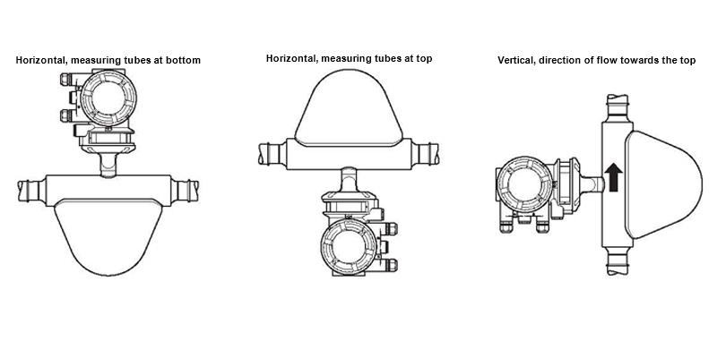
9. Location and position of installation