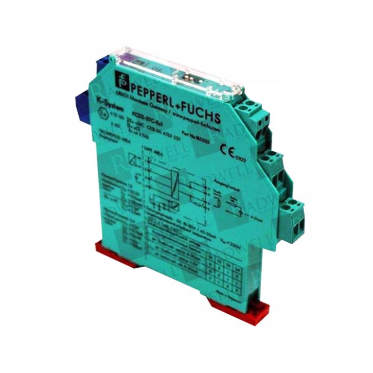
1. General Introduction
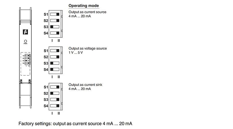
Pepperl+Fuchs Smart Transmitter Power Supply KCD2-STC-EX1 isolated barrier which is used for intrinsic safety applications. The device supplies 2-wire SMART transmitters in a hazardous area, and can also be used with 2-wire SMART current sources. It transfers the analog input signal to the safe area as an isolated current value. Digital signals may be superimposed on the input signal in the hazardous or safe area and are transferred bi-directionally. Selectable output of current source, sink mode, or voltage output is available via DIP switches. If the HART communication resistance in the loop is too low, the internal resistance of 250 Ω between terminals 6 and 8 can be used. Test sockets for the connection of HART communicators are integrated into the terminals of the device.
2. General Specification for KCD2-STC-EX1
Model | KCD2-STC-EX1 |
General specifications | |
Signal type | Analog input |
Functional safety related parameters | |
Safety Integrity Level (SIL) | SIL 2 |
Supply | |
Connection | Power Rail or terminals 9+, 10- |
Rated voltage Ur | 19 ... 30 V DC |
Ripple | ≤ 10 % |
Rated current Ir | ≤ 45 mA |
Power dissipation | ≤ 800 mW |
Power consumption | ≤ 1.1 W |
Input | |
Connection side | field side |
Connection | terminals 1+, 2-; 3+, 4- |
Input signal | 4 ... 20 mA limited to approx. 30 mA |
Open circuit voltage/short-circuit current | terminals 1+, 2-: 22 V / 30 mA |
Voltage drop | terminals 3+, 4- : approx. 5 V |
Available voltage | terminals 1+, 2-: ≥ 15 V at 20 mA |
Output | |
Connection side | control side |
Connection | terminals 5-, 6+ |
Load | 0 ... 300 Ω (source mode) |
Output signal | 4 ... 20 mA or 1 ... 5 V (on 250 Ω, 0.1 % internal shunt) 4 ... 20 mA (sink mode), operating voltage 15.5 ... 26 V |
Ripple | 20 mV rms |
Transfer characteristics | |
Deviation | at 20 °C (68 °F) ≤ ± 0.1 % incl. non-linearity and hysteresis (source mode 4 ... 20 mA) ≤ ± 0.2 % incl. non-linearity and hysteresis (sink mode 4 ... 20 mA) ≤ ± 0.2 % incl. non-linearity and hysteresis (source mode 1 ... 5 V) |
Influence of ambient temperature | < 2 μA/K (0 ... 60 °C (32 ... 140 °F)); < 4 μA/K (-20 ... 0 °C (-4 ... 32 °F)) (source mode and sink mode 4 ... 20 mA) < 0.5 mV/K (0 ... 60 °C (32 ... 140 °F)); < 1 mV/K (-20 ... 0 °C (-4 ... 32 °F)) (source mode 1 ... 5 V) |
Frequency range | field side into the control side: bandwidth with 0.5 Vpp signal 0 ... 3 kHz (-3 dB) control side into the field side: bandwidth with 0.5 Vpp signal 0 ... 3 kHz (-3 dB) |
Settling time | ≤ 200 ms |
Rise time/fall time | ≤ 20 ms |
Galvanic isolation | |
Input/Output | reinforced insulation acc. to EN 50178, rated insulation voltage 300 Veff |
Input/power supply | reinforced insulation acc. to EN 50178, rated insulation voltage 300 Veff |
Output/power supply | reinforced insulation acc. to EN 50178, rated insulation voltage 300 Veff |
Indicators/settings | |
Display elements | LED |
Control elements | DIP-switch |
Configuration | via DIP switches |
Labeling | space for labeling at the front |
Directive conformity | |
Electromagnetic compatibility | |
Directive 2014/30/EU | EN 61326-1:2013 (industrial locations) |
Conformity | |
Electromagnetic compatibility | NE 21:2006 |
Degree of protection | IEC 60529:2001 |
Ambient conditions | |
Ambient temperature | -20 ... 60 °C (-4 ... 140 °F) |
Mechanical specifications | |
Degree of protection | IP20 |
Connection | screw terminals |
Mass | approx. 100 g |
Dimensions | 12.5 x 114 x 124 mm (0.5 x 4.5 x 4.9 inch) , housing type A2 |
Mounting | on 35 mm DIN mounting rail acc. to EN 60715:2001 |
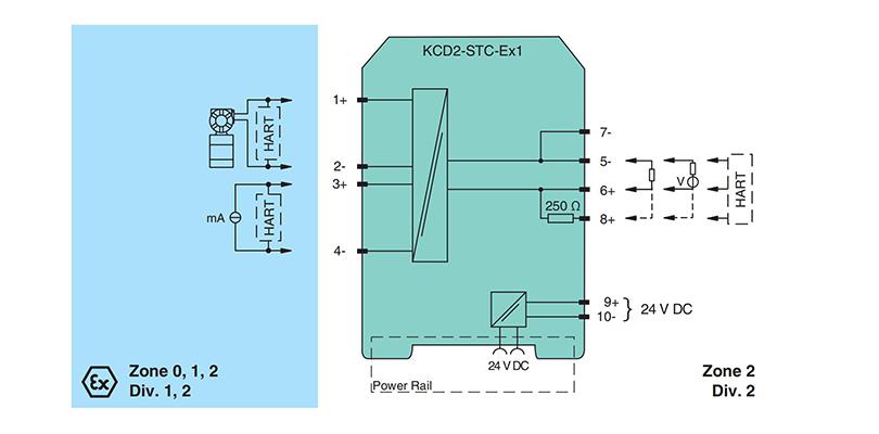
3. Connection
4. Configuration