1. General Introduction
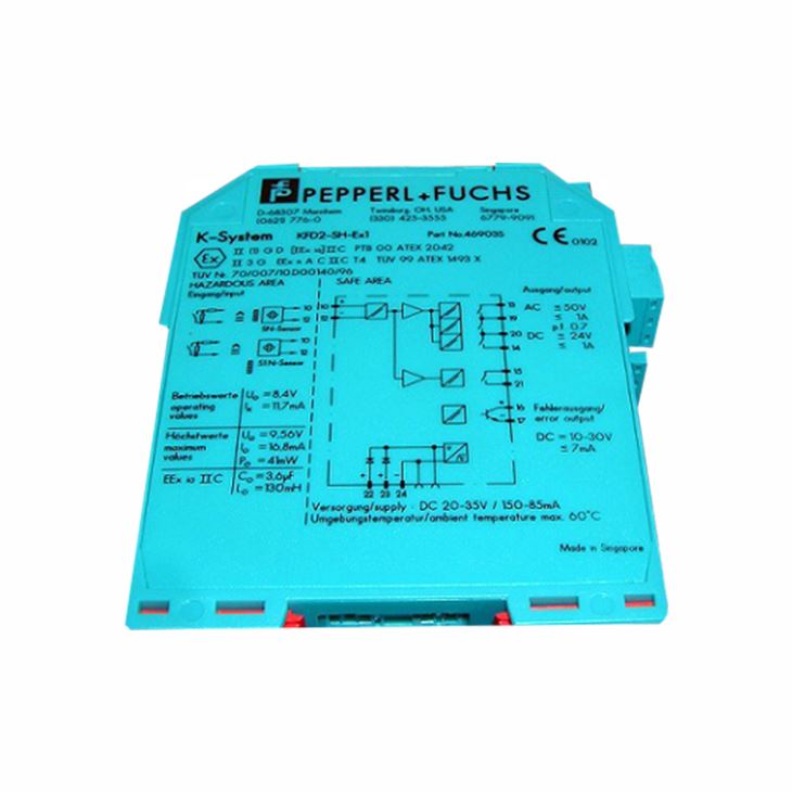
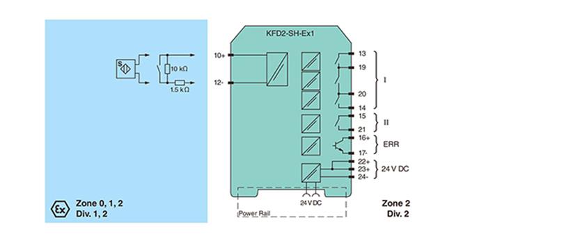
The input controls one relay contact output with 3 NO contacts (one output is in series to the both output relays for the safety function), one relay contact output with one NO contact, and one passive transistor output. Unlike an SN/S1N series proximity sensor, a mechanical contact, requires a 10 k resistor to be placed across the contact in addition to a 1.5 k resistor in series.
Lead breakage (LB) and short circuit (SC) conditions of the control circuit are continuously monitored. During an fault condition, the fault indication output energizes and outputs I and II de-energize. For safety applications up to SIL3, output I must be used. For
safety applications up to SIL2, output I and output II can be used.
2. General Specification for KFD2-SH-Ex1
Model | KFD2-SH-Ex1 |
General specifications | |
Signal type | Digital Input |
Functional safety related parameters | |
Safety Integrity Level (SIL) | SIL 3 |
Performance level (PL) | PL d |
Supply | |
Connection | Power Rail or terminals 22+, 23+, 24- |
Rated voltageUr | 20 ... 35 V DC |
Ripple | ≤10 % |
Rated current Ir | ≤130 mA |
Power dissipation | 2.1 W |
Power consumption | ≤2.3 W |
Input | |
Connection side | field side |
Connection | terminals 10+, 12- |
Open circuit voltage/short-circuit current | approx. 8.4 V DC / approx. 11.7 mA |
Lead resistance | ≤50 , in hazardous area cable capacitances and inductivities are to be taken into account |
Switching point | |
Relay de-energized | I < 2.1 mA and I > 5.9 mA |
Relay energized | 2.8 mA < I < 5.3 mA |
Response delay | ≤1 ms |
Output | |
Connection side | control side |
Connection | output I: terminals 13, 14 ; output II: terminals 15, 21 ; output III: terminals 16+, 17- |
Output I | relay , signal |
Contact loading | 50 V AC/1 A/cos > 0.7; 24 V DC/1 A resistive load |
Mechanical life | 50 x 106 switching cycles |
Output III | electronic output, passive , fault signal |
Rated voltage | 10 ... 30 V DC |
Signal level | 1-signal: (L+) -2.5 V (7 mA, short-circuit proof) / 0-signal: blocked output (Leakage current ≤10 mA) |
Transfer characteristics | |
Switching frequency | 5 Hz |
Galvanic isolation | |
Output/power supply | reinforced insulation according to IEC/EN 61010-1, rated insulation voltage 300 Veff |
Mutual output I, II, III | basic insulation according to IEC/EN 61010-1, rated insulation voltage 50 Veff |
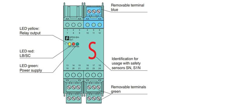
Indicators/settings | |
Display elements | LEDs |
Labeling | space for labeling at the front |
Directive conformity | |
Electromagnetic compatibility | |
Directive 2014/30/EU | EN 61326-1:2013 (industrial locations) |
Low voltage | |
Directive 2014/35/EU | EN 61010-1:2010 |
Machinery Directive | |
Directive 2006/42/EC | EN/ISO 13849-1:2008 |
Conformity | |
Electromagnetic compatibility | NE 21:2011 |
Degree of protection | IEC 60529:2001 |
Safety | IEC/EN 61508:2010 |
Ambient conditions | |
Ambient temperature | -20 ... 60 °C (-4 ... 140 °F) |
Mechanical specifications | |
Degree of protection | IP20 |
Connection | screw terminals |
Mass | approx. 280 g |
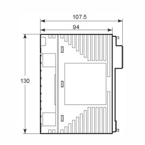
Dimensions | 40 x 107 x 115 mm (1.6 x 4.2 x 4.5 inch) , housing type C1 |
Mounting | on 35 mm DIN mounting rail acc. to EN 60715:2001 |
3. Connection
4. Configuration