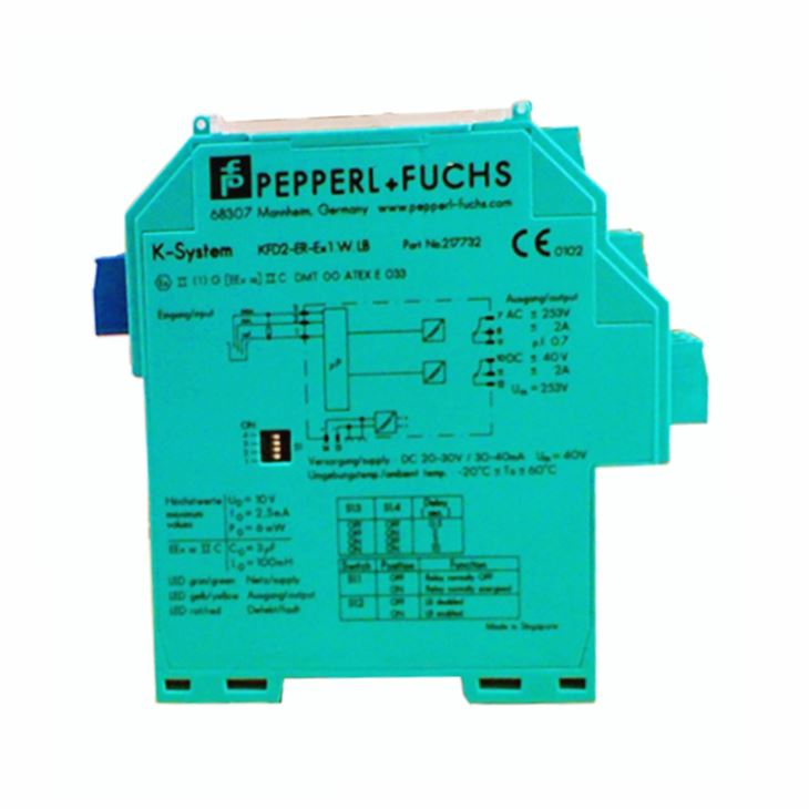
1. General Introduction
An overspeed or underspeed condition is signaled via the relay outputs. Line fault detection of the field circuit is indicated by a red LED, Power Rail and relay. The startup override feature sets relay outputs to default conditions programmed by the user for up to 1,000 seconds. The unit is easily programmed by the use of a keypad located on the front of the unit. A unique collective error messaging feature is available when used with the Power Rail system. For additional information, refer to the manual .
2. General Specification for KFD2-DWB-1.D
Model | KFD2-DWB-1.D |
General specifications | |
Signal type | Digital Input |
Functional safety related parameters | |
Safety Integrity Level (SIL) | SIL 2 |
Supply | |
Connection | terminals 23+, 24- or power feed module/Power Rail |
Rated voltage Ur | 20 ... 30 V DC |
Rated current Ir | approx. 100 mA |
Power dissipation/power consumption | ≤ 1.8 W / 1.8 W |
Input | |
Connection side | field side |
Connection | Input I: 2-wire sensor: terminals 1+, 3- three wire sensor: terminals 1+, 2- and 3 input II: terminals 13+, 14- start-up override; |
Input I | 2- or 3-wire sensor, sensor acc. to EN 60947-5-6 (NAMUR) or mechanical contact |
Open circuit voltage/short-circuit current | 22 V / 40 mA |
Input resistance | 4.7 kΩ |
Switching point/switching hysteresis | logic 1: > 2.5 mA ; logic 0: < 1.9 mA |
Pulse duration | > 50 μs |
Input frequency | 0.001 ... 12000 Hz |
Line fault detection | breakage I ≤ 0.15 mA; short-circuit I > 4 mA |
Input II | startup override: 1 ... 1000 s, adjustable in steps of 1 s |
Active/Passive | I > 4 mA (for min. 100 ms) / I < 1.5 mA |
Open circuit voltage/short-circuit current | 18 V / 5 mA |
Output | |
Connection side | control side |
Connection | output I: terminals 10, 11, 12 output II: terminals 16, 17, 18 |
Output I, II | signal, relay |
Contact loading | 250 V AC / 2 A / cos φ ≥ 0.7 ; 40 V DC / 2 A |
Mechanical life | 5 x 10⁷ switching cycles |
Energized/De-energized delay | approx. 20 ms / approx. 20 ms |
Collective error message | Collective error message |
Transfer characteristics | |
Input I | |
Measurement range | 0.001 ... 12000 Hz |
Resolution | 0.1 % of measured value , ≥ 0.001 Hz |
Accuracy | 0.1 % of measured value , > 0.001 Hz |
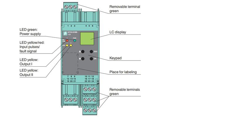
Indicators/settings | |
Display elements | LEDs , display |
Control elements | Control panel |
Directive conformity | |
Electromagnetic compatibility | |
Directive 2014/30/EU | EN 61326-1:2013 (industrial locations) |
Low voltage | |
Directive 2014/35/EU | EN 61010-1:2010 |
Conformity | |
Electromagnetic compatibility | NE 21:2006 |
Degree of protection | IEC 60529:2001 |
Ambient conditions | |
Ambient temperature | -20 ... 60 °C (-4 ... 140 °F) |
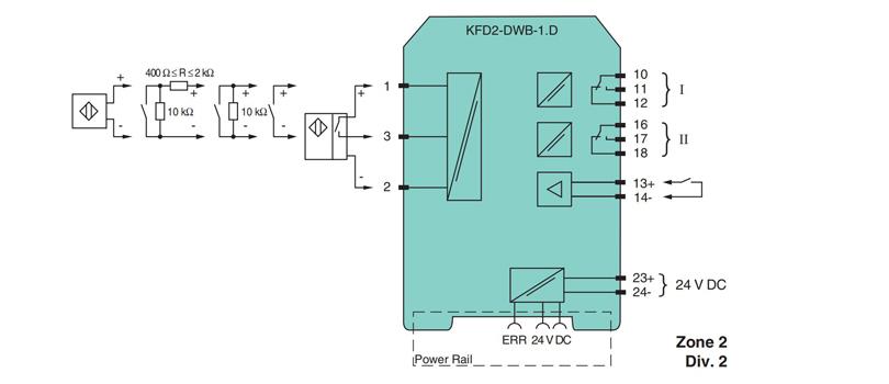
3. Connection
4. Assembly