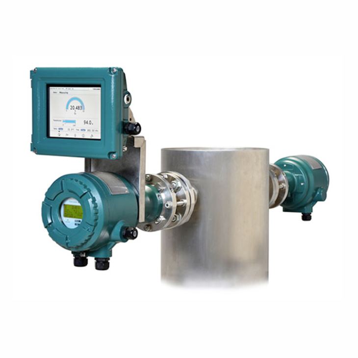
1.General Introduction
Yokogawa TDLS8000 Tunable Diode Laser Spectrometer measure concentration of O2, CO, CH4, NH3, H2O and many more NIR absorbing gases, Its platform design is for in situ measurements which negate the need for sample extraction and conditioning. The non-contacting sensor allows for a variety of process types including corrosive, abrasive and condensing. TDLS8000 is the second generation platform has improved reliability and ease of installation and maintenance while still meeting or exceeding designed application demands. YH8000 10 language display is optional.
2.Measurable Gas Components and Ranges
Component | TDLS8000 Tunable Diode Laser Spectrometer | |
Min. range | Max. range | |
O2 | 0-1% | 0-25% |
CO(ppm) | 0-200ppm | 0-10000ppm |
CO | 0-200ppm | 0-10000ppm |
CH4 | 0-5% | 0-5% |
NH3 | 0-30ppm | 0-5000ppm |
H2O(ppm) in non HC | 0-30ppm | 0-30000ppm |
CO (%) | 0-20% | 0-50% |
CO (%) + CO2 (%) | 0-30% | 0-100% |
H2S | 0-5% | 0-100% |
CO2 (%) High Range | 0-1% | 0-5% |
CO2 (%) Extend. Range | 0-30% | 0-50% |
H2O (%) | 0-10% | 0-100% |
HCI | 0-50ppm | 0-5000ppm |
3.Model Selection of TDLS8000 Tunable Diode Laser Spectrometer
Main Code | Suffix Codes | Description | ||||||
TDLS8000 | Tunable Diode Laser Spectrometer | |||||||
Type | -G1 | General Purpose, cable entry/piping: NPT | ||||||
-G2 | General Purpose, cable entry: Metric thread, piping: Rc | |||||||
-GQ | EAC with PA General Purpose, cable entry: Metric thread, piping: Rc | |||||||
-GR | EAC General Purpose, cable entry: Metric thread, piping: Rc | |||||||
-D2 | FM (US) Class I Div 2, Zone2, cable entry/piping: NPT | |||||||
-C2 | FM (Canada) Class I Zone2, cable entry/piping :NPT | |||||||
-S2 | ATEX Type of protection “n”, cable entry: Metric thread, piping: Rc | |||||||
-E2 | IECEx Type of protection “n”, cable entry: Metric thread, piping: Rc | |||||||
-K2 | KOSHA Type of protection “n”, cable entry: Metric thread, piping: Rc | |||||||
-N2 | NEPSI Type of protection “n”, cable entry: Metric thread, piping: Rc | |||||||
-Q2 | EAC with PA Type of protection “n”, cable entry: Metric thread, piping: Rc | |||||||
-R2 | EAC Type of protection “n”, cable entry: Metric thread, piping: Rc | |||||||
-D1 | FM (US) Class I Div 1, Zone1, cable entry /piping: NPT | |||||||
-C1 | FM (Canada) Class I Zone1, cable entry/piping: NPT | |||||||
-S1 | ATEX Flameproof ”d”, cable entry: Metric thread, piping: Rc | |||||||
-E1 | IECEx Flameproof “d”, cable entry: Metric thread, piping: Rc | |||||||
-J1 | Japan Ex / Zone 1, cable entry: Metric thread, piping: Rc | |||||||
-J2 | Japan Ex / Zone 2, cable entry: Metric thread, piping: Rc | |||||||
-Q1 | EAC with PA Flameproof “d”, cable entry: Metric thread, piping: Rc | |||||||
-R1 | EAC Flameproof “d”, cable entry: Metric thread, piping: Rc | |||||||
Gas Parameter | -X1 | O2 < 600°C, 0-25% | ||||||
-X2 | O2 < 1500°C, 0-25% Combustion | |||||||
-C1 | CO (%) 0-20%/0-50% <500°C | |||||||
-C2 | CO ppm 0-200ppm/0-10,000ppm <500°C | |||||||
-C3 | CO ppm <1500°C Combustion | |||||||
-C4 | CO ppm <1500°C or CH4 0-5% Combustion | |||||||
-C5 | CO (%) + CO2(%) 0-30%/0-100% <150°C | |||||||
-A1 | NH3 up to 0-5,000ppm <450°C | |||||||
-S1 | H2S 0-5%/0-100% <100°C | |||||||
-D1 | CO2 High Range 0-1%/0-5% <100°C | |||||||
-D5 | CO2 Extend. Range 0-30/0-50% <150°C | |||||||
-H1 | H2O ppm non-Hydrocarbon Background | |||||||
-H4 | H2O 0-10%/0-100% <500°C | |||||||
-L1 | HCl 0-50ppm/0-5,000ppm <500°C | |||||||
Optics Accessory | -NN | Without Alignment Flanges | ||||||
-LA | Large Aperture Optics, ANSI CLASS150-4-RF | |||||||
-U2 | ANSI CLASS150-2-RF(Eq.) Alignment Flange, piping: NPT | |||||||
-U3 | ANSI CLASS150-3-RF(Eq.) Alignment Flange, piping: NPT | |||||||
-U4 | ANSI CLASS150-4-RF(Eq.) Alignment Flange, piping: NPT | |||||||
-D5 | DIN PN16-DN50-D(Eq.) Alignment Flange, piping: Rc | |||||||
-D8 | DIN PN16-DN80-D(Eq.) Alignment Flange, piping: Rc | |||||||
-J5 | JIS 10K-50-FF(Eq.) Alignment Flange, piping: Rc | |||||||
-J8 | JIS 10K-80-FF(Eq.) Alignment Flange, piping: Rc | |||||||
-FC | Flow Cell Alignment Flange | |||||||
I/O Interface | -A1 | Analog with HART+Modbus Ethernet | ||||||
SI Unit | -J | Only SI Unit | ||||||
-N | SI Unit or non SI Unit | |||||||
— | -N | Always -N | ||||||
Options | /D | Diverging Beam without LAO | ||||||
/RX | Reference Cell for O2 | |||||||
/RC | Reference Cell for CO | |||||||
/SCT | Stainless Steel Tag Plate | |||||||
/JA1 | Cable gland for Japan Ex “-J1” (Cable O.D. 8-12mm, G1/2) 1pc, for local HMI | |||||||
/JB3 | Cable gland for Japan Ex “-J1” (Cable O.D. 10-16mm, G3/4) 3pcs | |||||||
/JB4 | Cable gland for Japan Ex “-J1” (Cable O.D. 10-16mm, G3/4) 4pcs | |||||||
/JC1 | Cable gland for Japan Ex “-J2” (Cable O.D. 6-9.5mm, M20) 1pc, for local HMI | |||||||
/JD1 | Cable gland for Japan Ex “-J2” (Cable O.D. 8.5-13.4mm, M20) 1pc, for local HMI | |||||||
/JE3 | Cable gland for Japan Ex “-J2” (Cable O.D. 9.5-15.4mm, M25) 3pcs | |||||||
/JE4 | Cable gland for Japan Ex “-J2” (Cable O.D. 9.5-15.4mm, M25) 4pcs | |||||||
4.Model Selection of YH8000 HMI Unit
Main Code | Suffix Codes | Description | |||
YH8000 | HMI Unit | ||||
Type | -G1 | General Purpose, NPT thread for cable entry | |||
-G2 | General Purpose, Metric thread for cable entry | ||||
-GR | EAC General Purpose, Metric thread for cable entry | ||||
-D2 | FM (US) Class I Div 2, Zone2, NPT thread for cable entry | ||||
-C2 | FM (Canada) Class I Zone2, NPT thread for cable entry | ||||
-S2 | ATEX Type of protection “n”, Metric thread for cable entry | ||||
-E2 | IECEx Type of protection “n”, Metric thread for cable entry | ||||
-J2 | Japan Ex / Zone 2, Metric thread for cable entry | ||||
-K2 | KOSHA Type of protection “n”, Metric thread for cable entry | ||||
-N2 | NEPSI Type of protection “n”, Metric thread for cable entry | ||||
-R2 | EAC Type of protection “n”, Metric thread for cable entry | ||||
Language | -E | English and 9 languages | |||
— | -N | Always -N | |||
Options | /M | Mounting kit for TDLS8000 | |||
/P | Pipe mount | ||||
/W | Wall mount | ||||
/S | Sun Shield | ||||
/C | Local HMI connection cable: 3m | ||||
/SCT | Stainless Steel Tag Plate | ||||
/JA1 | Cable gland for Japan Ex (Cable O.D. 8-12mm, G1/2), 1pc | ||||
/JA2 | Cable gland for Japan Ex (Cable O.D. 8-12mm, G1/2), 2pcs | ||||
5.Model Selection of IF8000 Isolation Flanges
Main Code | Suffix Codes | Description | ||||
IF8000 | Isolation Flange for TDLS8000 (2pcs/unit) | |||||
Process Connection | -21 | ANSI CLASS150-2-RF(Eq.) | ||||
-23 | ANSI CLASS300-2-RF(Eq.) | |||||
-31 | ANSI CLASS150-3-RF(Eq.) | |||||
-33 | ANSI CLASS300-3-RF(Eq.) | |||||
-41 | ANSI CLASS150-4-RF(Eq.) | |||||
-50 | DIN PN16-DN50-D(Eq.) | |||||
-80 | DIN PN16-DN80-D(Eq.) | |||||
-J5 | JIS 10K-50-FF(Eq.) | |||||
-J8 | JIS 10K-80-FF(Eq.) | |||||
Analyzer Connection | -21 | ANSI CLASS150-2-RF(Eq.) | ||||
-50 | DIN PN16-DN50-D(Eq.) | |||||
Material | -MN | Monel 400 | ||||
-SS | 316/316L SS | |||||
Sapphire Window Type | -12 | Coated for O2 (-X1, -X2) | ||||
-13 | Coated for ppmH2O non Hydrocarbon background (-H1) | |||||
-14 | Coated for ppmNH3 (-A1) | |||||
-16 | Coated for ppm CO (-C2, -C3, -C4) | |||||
-17 | Coated for %CO or %CO2 (-C5, -D5) | |||||
-18 | Coated for HCl (-L1) | |||||
-20 | Coated for -C1, -D1, -H4, -S1 | |||||
— | -N | Always -N | ||||
6.Model Selection of YC8000 Flow Cell
Main Code | Suffix Codes | Description | ||||||
YC8000 | Flow Cell for TDLS8000 | |||||||
Flow Cell Type | -EN | Enhanced | ||||||
Optical Path Length | -40 | Forty Inches | ||||||
-60 | Sixty Inches | |||||||
Material | -MN | Monel 400 | ||||||
-SS | 316/316L SS | |||||||
Port Configuration | -3 | 3 ports | ||||||
Window Type | -XX | Oxygen (-X1, -X2) | ||||||
-HH | Moisture non Hydrocarbon background (-H1) | |||||||
-NH | NH3 (-A1) | |||||||
-CC | ppm CO (-C2, -C3, -C4) | |||||||
-C2 | CO%+CO2% (-C5, -D5) | |||||||
-HC | HCl (-L1) | |||||||
-MC | -C1, -D1, -H4, -S1 | |||||||
Inside Wall Treatment | -NN | No treatment (cleaned) | ||||||
-EP | Electro-polish | |||||||
— | -N | Always -N | ||||||
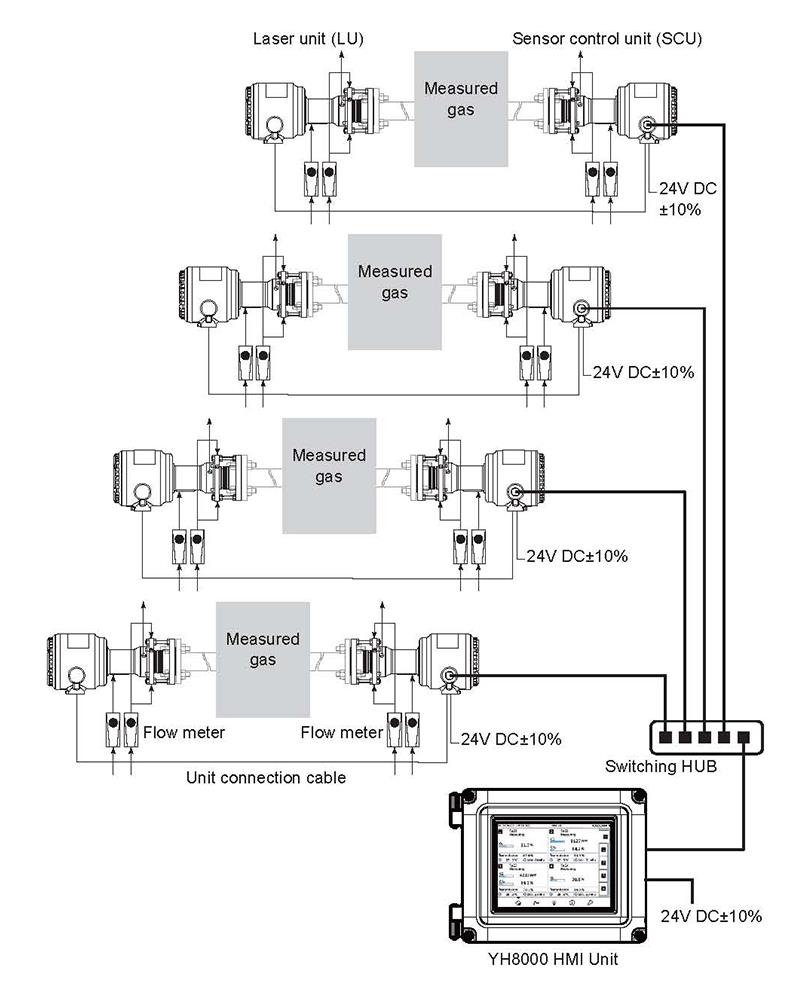
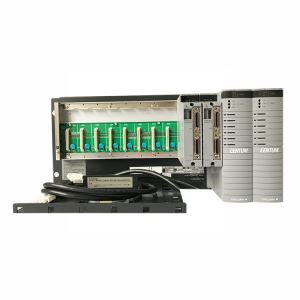
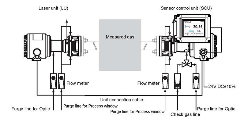
7.Typical System Configuration

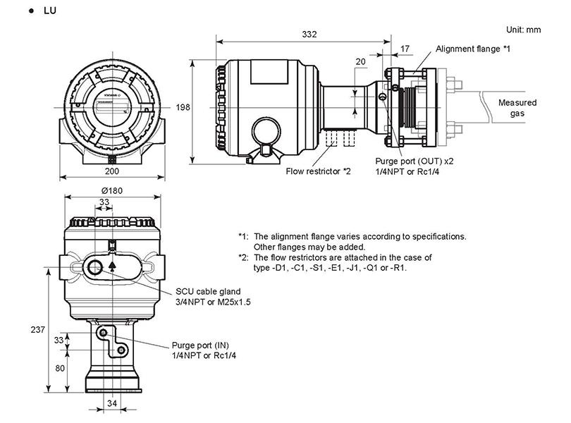
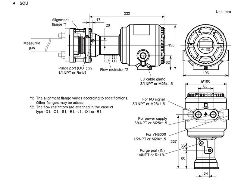
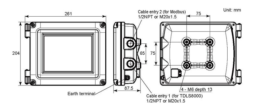
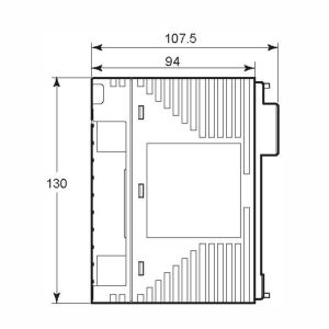
8. External Dimensions