1. General Introduction
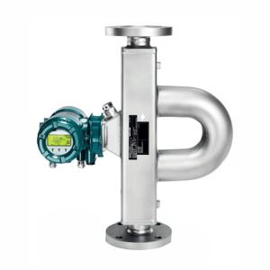
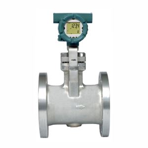
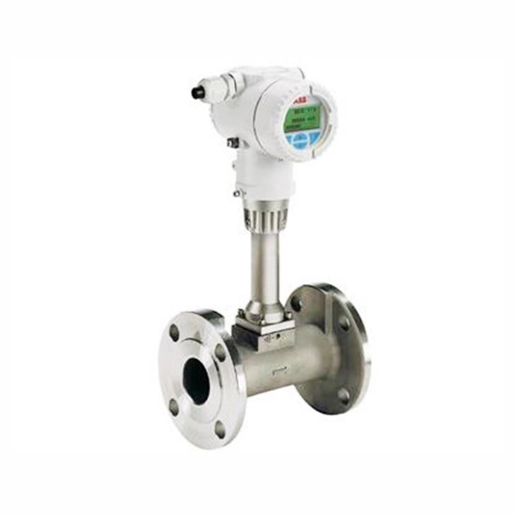
ABB FSV430 flow meters can be used for accurate measurement of the flow of gases, liquids and steam over a wide range of temperatures. Vortex meters are ideal for use on petrochemical raw materials, dematerialized water and for direct, cost- effective steam mass flow by employing integral temperature measurement. Moreover, VortexMaster FSV430 is the standard design with optional digital outputs, graphical display and excellent vibration immunity for a wide field of applications also available with integral or remote transmitter with up to 30m (98 ft.) signal cable.
2. Compare table of FSV430 and FSV450
Model | FSV430 | FSV450 |
Design (sensor) | Compact design, remote mount design | |
IP degree of protection in accordance with EN 60529 | IP 66 / 67, NEMA 4X | |
Measuring accuracy for liquids | ≤ ±0.65 % under reference conditions | |
Measuring accuracy for gases and vapors | ≤ ±0.9 % under reference conditions | |
Reproducibility | DN 15 (1/2") ≤ ±0.3 %, DN 15 (1/2") up to DN 150 (6") ≤ ±0.2 %, from DN 200 (8") ≤ ±0.25 % | |
Permissible viscosity for liquids | DN 15 (1/2") ≤ 4 mPa s, DN 25 (1") ≤ 5 mPa s, from DN 40 (1 1/2") ≤ 7.5 mPa s | |
Measuring span (typical) | 1:20 | |
Process connections | — Flange: DN 15 ... 300 (1/2 ... 12") — Wafer type: DN 25 ... 150 (1" ... 6") " | |
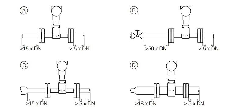
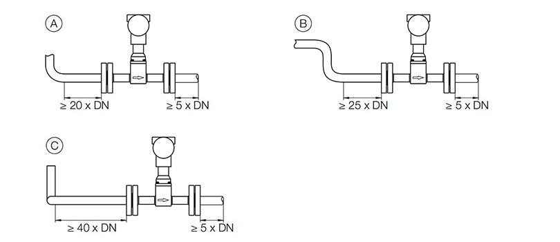
Inlet/outlet sections (typical) | Inlet section: 15 x DN, outlet section 5 x DN, see also chapter Inlet and outlet sections" on page 11. " | |
Temperature measurement | Resistance thermometer Pt100 class A optional, installed in Piezo sensor, can be retrofitted | Resistance thermometer Pt100 class A standard, fixed installation in Piezo sensor |
Permissible measuring medium temperature | Standard: -55 ... 280 ºC (-67 ... 536 ºF), optional:.-55 ... 400 ºC (-67 ... 752 ºF) (high temperature design) | -55 … 280 ºC (-67 … 536 ºF) |
Wetted material | ||
Sensor | Stainless steel, optional Hastelloy C | |
Gasket | PTFE, optional Kalrez or graphite | |
Sensor housing | Stainless steel, optional Hastelloy C, carbon steel | |
Sensor design | Piezo sensor with two pairs of sensors for flow measurement and vibration compensation | |
Approvals for explosion protection | ATEX / IECEx, cFMus, NEPSI | |
Display (transmitter) | Optional LCD indicator with 4 push buttons for operation through front glass (option) | Standard LCD indicator with 4 push buttons for operation through front glass |
Operating modes | ||
Liquids | Operating volume, standard volume, mass | Operating volume, standard volume, mass, energy |
Gases | Operating volume, standard volume, mass | Operating volume, standard volume, mass, energy |
Biogas | — | Operating volume, standard volume |
Steam | Operating volume, mass | Operating volume, mass, energy |
Digital output | Optional, can be configured as pulse output, frequency output or alarm output via software | Standard, can be configured as pulse output, frequency output or alarm output via software |
Inputs for external sensors | — HART input for external pressure or temperature transmitter communicating in HART burst mode | — Analog input 4 ... 20 mA for external pressure- / temperature transmitter or gas analyzer — HART input for external pressure- / temperature transmitter or gas analyzer communicating in HART burst mode |
Current output, communication | 4 ... 20 mA, HART protocol (HART 7), Modbus RTU-RS485 | 4 ... 20 mA, HART protocol (HART 7) |
Power supply | HART communication: 12 ... 42 V DC, Modbus communication: 9 ... 30 V DC | |
SensorMemory | Saves sensor & process parameters for easy start up after transmitter exchange | |
Housing material | — Aluminum (copper content < 0.3 %), component epoxy coating — Optional: stainless steel CF3M, corresponds to AISI 316L — Tower: CF8, complies with AISI 304 | |
IP rating in accordance with EN 60529 | IP 66, IP 67, NEMA 4X | |
3. Flow Measurement for Liquids
Nominal Diameter | Minimum Reynolds number | QmaxDN | Frequency for Qmax [Hz, ±5 %] | ||
Re1 | Re2 | [m3/h] | [Usgpm] | ||
DN 15 (1/2 ”) | 11300 | 20000 | 7 | 31 | 430 |
DN 25 (1 ”) | 13100 | 20000 | 18 | 79 | 247 |
DN 40 (1 1/2 ”) | 15300 | 20000 | 48 | 211 | 193 |
DN 50 (2 ”) | 15100 | 20000 | 75 | 330 | 155 |
DN 80 (3 ”) | 44000 | 44000 | 170 | 749 | 101 |
DN 100 (4 ”) | 36400 | 36400 | 270 | 1189 | 73 |
DN 150 (6 ”) | 58000 | 58000 | 630 | 2774 | 51 |
DN 200 (8 ”) | 128000 | 128000 | 1100 | 4844 | 40 |
DN 250 (10 ”) | 100000 | 100000 | 1800 | 7926 | 33 |
DN 300 (12 ”) | 160000 | 160000 | 2600 | 11449 | 28 |
4. Flow Measurement of Gases and Vapors
Nominal Diameter | Flange | Minimum Reynolds number | QmaxDN | Frequency for Qmax [Hz, ±5 %] | ||
Re1 | Re2 | [m3/h] | [Usgpm] | |||
DN 15 (1/2 ”) | DIN | 4950 | 10000 | 24 (42) | 14.3 (25) | 1510 (2640) |
ASME | 22 (36) | 13.1 (21) | 1830 (3000) | |||
DN 25 (1 ”) | DIN | 6600 | 10000 | 150 (150) | 88 (88) | 2040 (2040) |
ASME | 82 (130) | 48 (76) | 1870 (3000) | |||
DN 40 (1 1/2 ”) | DIN | 6750 | 10000 | 390 (390) | 230 (230) | 1580 (1580) |
ASME | 340 (340) | 200 (230) | 1960 (1960) | |||
DN 50 (2 ”) | DIN | 9950 | 20000 | 500 (500) | 294 (294) | 1040 (1040) |
ASME | 450 (450) | 265 (265) | 1230 (1230) | |||
DN 80 (3 ”) | DIN | 13000 | 20000 | 1200 (1380) | 706 (812) | 720 (820) |
ASME | 950 (1380) | 559 (812) | 770 (1120) | |||
DN 100 (4 ”) | DIN | 16800 | 20000 | 1900 (2400) | 1119 (1413) | 510 (640) |
ASME | 1800 (2400) | 1059 (1413) | 640 (850) | |||
DN 150 (6 ”) | DIN | 26500 | 27000 | 4500 (5400) | 2648 (3178) | 360 (430) |
ASME | 4050 (5400) | 2382 (3178) | 410 (540) | |||
DN 200 (8 ”) | DIN | 27600 | 28000 | 8000 (9600) | 4708 (5650) | 290 (350) |
ASME | 6800 (9600) | 4000 (5650) | 290 (420) | |||
DN 250 (10 ”) | DIN | 41000 | 41000 | 14000 (16300) | 8240 (9594) | 250 (290) |
ASME | 12000 (16300) | 7059 (9594) | 240 (320) | |||
DN 300 (12 ”) | DIN | 48000 | 48000 | 20000 (23500) | 11765 (13832) | 220 (260) |
ASME | 17000 (23500) | 10006 (13832) | 190 (270) | |||
5. Temperature Range of Different Materials for the Sensor and Transmitter
Materials | Temperature range Tmedium |
Wetted components (Materials for the sensor) | |
Meter tube: — Stainless steel 1.4571 (AISI 316 Ti) / AISI 316L / CF8 / CF8C — Hastelloy C-4 (optional) — Carbon steel (optional) | -55 ... 400 ºC (-67 ... 752 ºF) |
Sensor: — Stainless steel 1.4571 (AISI 316 Ti) — Hastelloy C-4 (optional) | -55 ... 280 ºC (-67 ... 536 ºF) |
-55 ... 400 ºC (-67 ... 752 ºF) | |
Sensor gasket:1) — PTFE O-ring — Kalrez 6375 O-ring (optional) — Graphite (optional for hightemperature design) | -55 ... 260 ºC (-67 ... 500 ºF) |
-20 ... 275 ºC (-4 ... 527 ºF) | |
-55 ... 400 ºC (-67 ... 752 ºF) | |
Housing (Materials for the transmitter) | |
— Die-cast aluminum, copper content < 0.3 % — Stainless steel CF3M, corresponds to AISI 316L (optional) — Tower: CF8, complies with AISI 304 | -40 ... 85 ºC (-67 ... 185 ºF) |
6. Basic Code Selection of FSV430 and FSV450
Main Code | Suffix Codes | Description | ||||||
FSV430 FSV450 | Always FSV430, FSV450 | |||||||
Explosion Protection Certification | Y0 | Without | ||||||
B1 | ATEX Ex nA / Ex tc (Zone 2 und 22) | |||||||
A4 | ATEX Ex ia / Ex ia (Zone 0 und 20) | |||||||
A9 | ATEX Ex d ia / Ex tb (Zone 0/1 und 21) | |||||||
B8 | ATEX kombiniert B1 + A4 (Ex n + Ex ia) | |||||||
B9 | ATEX kombiniert B1 + A4 + A9 (Ex n + Ex ia + Ex d) | |||||||
N1 | IECEx Ex nA / Ex tc (Zone 2 und 22) | |||||||
N2 | IECEx Ex ia / Ex ia (Zone 0 und 20) | |||||||
N3 | IECEx Ex d ia / Ex tb (Zone 0/1 und 21) | |||||||
N8 | IECEx kombiniert N1 + N2 (Ex n + Ex ia) | |||||||
N9 | IECEx kombiniert N1 + N2 + N3 (Ex n + Ex ia + Ex d) | |||||||
F1 | cFMus XP Cl I,II,III Div 1 / Zone 1 | |||||||
F4 | cFMus IS Cl I,II,III Div 1 / Zone 0 | |||||||
F3 | cFMus NI Cl I Div 2, Cl II,III Div 1,2 / Zone 2 | |||||||
F8 | cFMus kombiniert F3 + F4 (Ex n + Ex ia) | |||||||
F9 | cFMus kombiniert F3 + F4 + F1 (Ex n + Ex ia + Ex d) | |||||||
S2 | NEPSI Ex nA / DIP A22 (Zone 2 und 22) | |||||||
S6 | NEPSI Ex ia / Ex iaD (Zone 0 und 20) | |||||||
S1 | NEPSI Ex d ia / DIP A21 (Zone 0/1 und 21) | |||||||
S8 | NEPSI kombiniert N1 + N2 (Ex n + Ex ia) | |||||||
S9 | NEPSI kombiniert N1 + N2 + N3 (Ex n + Ex ia + Ex d) | |||||||
System Design | C1 | Integral single sensor | ||||||
R1 | Remote single sensor, 5 m ( 16 ft) signal cable included | |||||||
C2 | Integral dual sensor | |||||||
R2 | Remote dual sensor, 2 x 5 m ( 16 ft) signal cable included | |||||||
Process Connection Type / Meter Size / Connection Size | W025R0 | Wafer / DN 25 (1 in.) / DN 25 (1 in.) | ||||||
W040R0 | Wafer / DN 40 (1-1/2 in.) / DN 40 (1-1/2 in.) | |||||||
W050R0 | Wafer / DN 50 (2 in.) / DN 50 (2 in.) | |||||||
W080R0 | Wafer / DN 80 (3 in.) / DN 80 (3 in.) | |||||||
W100R0 | Wafer / DN 100 (4 in.) / DN 100 (4 in.) | |||||||
W150R0 | Wafer / DN 150 (6 in.) / DN 150 (6 in.) | |||||||
F015R0 | Flange / DN 15 (1/2 in.) / DN 15 (1/2 in.) | |||||||
F025R0 | Flange / DN 25 (1 in.) / DN 25 (1 in.) | |||||||
F040R0 | Flange / DN 40 (1-1/2 in.) / DN 40 (1-1/2 in.) | |||||||
F050R0 | Flange / DN 50 (2 in.) / DN 50 (2 in.) | |||||||
F080R0 | Flange / DN 80 (3 in.) / DN 80 (3 in.) | |||||||
F100R0 | Flange / DN 100 (4 in.) / DN 100 (4 in.) | |||||||
F150R0 | Flange / DN 150 (6 in.) / DN 150 (6 in.) | |||||||
F200R0 | Flange / DN 200 (8 in.) / DN 200 (8 in.) | |||||||
F250R0 | Flange / DN 250 (10 in.) / DN 250 (10 in.) | |||||||
F300R0 | Flange / DN 300 (12 in.) / DN 300 (12 in.) | |||||||
Pressure Rating | D1 | PN 10 | ||||||
D2 | PN 16 | |||||||
D3 | PN 25 | |||||||
D4 | PN 40 | |||||||
D5 | PN 63 | |||||||
D6 | PN 100 | |||||||
D7 | PN 160 | |||||||
A1 | ASME CL 150 | |||||||
A3 | ASME CL 300 | |||||||
A6 | ASME CL 600 | |||||||
A7 | ASME CL 900 | |||||||
J0 | JIS 7.5K | |||||||
J1 | JIS 10K | |||||||
J2 | JIS 5K | |||||||
J3 | JIS 20K | |||||||
J4 | JIS 30K | |||||||
Z9 | Others | |||||||
Temperature Range of Measuring Medium | A1 | Standard -55 ... 280 ºC (-67 ... 536 ºF) | ||||||
B1 | Extended -55 ... 400 ºC (-67 ... 752 ºF) | |||||||
Housing Material / Cable Glands | A1 | Aluminium / 2 pcs. metric, M20 x 1.5, cable glands mounted | ||||||
B1 | Aluminium / 2 pcs. 1/2 in. NPT threads, cable glands not included | |||||||
S1 | Stainless steel 316L / 2 pcs. metric, M20 x 1.5, cable glands mounted | |||||||
T1 | Stainless steel 316L / 2 pcs. 1/2 in. NPT threads, cable glands not included | |||||||
Output Signal | H1 | HART digital communication and 4 ... 20 mA | ||||||
H5 | HART digital communication, 4 ... 20 mA + digital contact output | |||||||
M4 | Modbus communication with digital contact output | |||||||
7. Straight Runner of Upstream and Downstream
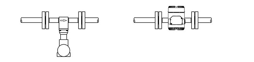
8. Installation at High Measuring Medium Temperatures
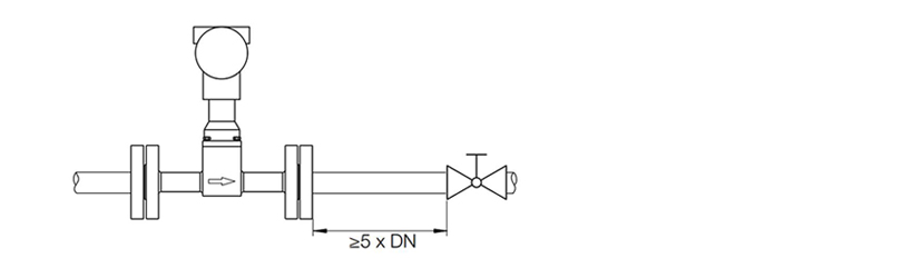
9. Final Controlling Equipment Must Be Arranged Downstream of the Flowmeter
10. Insulation of the meter tube

Copyright © Rostock Group Co.,Limited All Rights Reserved. Sitemap
 QR Code