1. General Introduction
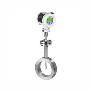
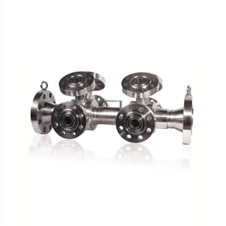
ABB FPD470 Wedge flowmeter is mainly applicable for high viscosity liquid and slurries which not able to be measured by traditional flow meters. Its flow elements utilize V-shaped restrictions to produce a square root relationship between differential pressure and volumetric flow. Elements are designed for either clean or dirty service and are offered in various materials, pipe sizes, and pressure ratings. The differential pressure is measured by a differential pressure transmitter. The flow element consists of a body and wedge flow restriction. This restriction creates a differential pressure in proportion to the square of the volumetric flow rate.
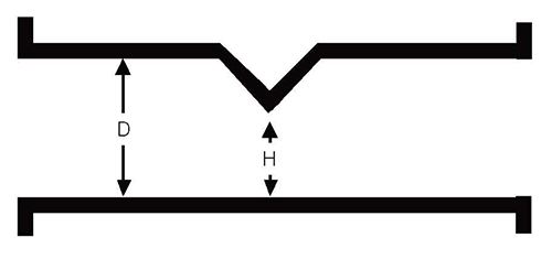
2. WEDGE element standard H/D ratios
| |||
PIpe size (in.) | Wedge ratio (H/D) | Calibrated Accuracy | Un-calibrated Accuracy |
1/2 inch | 0.2, 0.3, 0.4, 0.5 | 0.75 % | +5 % |
1 and 1-1/2 inch | 0.2, 0.3, 0.4, 0.5 | 0.5 % | +5 % |
2 and 3 inch | 0.2, 0.3, 0.4, 0.5 | 0.5 % | +5 % |
4 to 20 inch | 0.3, 0.4, 0.5, 0.6, 0.7 | 0.5 % | +5 % |
3. Model selection
Model | Suffix Codes | Description | ||||||||||||
FPD470 | FPD470 Wedge flowmeter | |||||||||||||
Product design | P | Pipe-tap | ||||||||||||
F | Flanged taps | |||||||||||||
C | Chemical tee taps | |||||||||||||
Restriction design | W1 | Single wedge | ||||||||||||
Line nominal bore | 015 | DN 15 (1/2 in.) | ||||||||||||
XXX | DNXXX, Up to DN 950 (38 in.) | |||||||||||||
001 | DN 1000 (40 in.) | |||||||||||||
051 | DN 1050 (42 in.) | |||||||||||||
101 | DN 1100 (44 in.) | |||||||||||||
151 | DN 1150 (46 in.) | |||||||||||||
201 | DN 1200 (48 in.) | |||||||||||||
999 | Others | |||||||||||||
Pipe schedule | S2 | Schedule 5 | ||||||||||||
S4 | Schedule 10 | |||||||||||||
S5 | Schedule 20 | |||||||||||||
S6 | Schedule 30 | |||||||||||||
S8 | Schedule 40 | |||||||||||||
T1 | Schedule 60 | |||||||||||||
T3 | Schedule 80 | |||||||||||||
Z9 | Others | |||||||||||||
Pipe material | C3 | Carbon steel | ||||||||||||
S6 | 316 / 316L stainless steel | |||||||||||||
S4 | 304 / 304L stainless steel | |||||||||||||
H6 | 316H stainless steel | |||||||||||||
S2 | 321 stainless steel | |||||||||||||
S9 | 904L stainless steel | |||||||||||||
U7 | Alloy C-276 | |||||||||||||
L1 | Tantalum | |||||||||||||
Z9 | Others | |||||||||||||
Restriction material | C3 | Carbon steel | ||||||||||||
S6 | 316 / 316L stainless steel | |||||||||||||
S4 | 304 / 304L stainless steel | |||||||||||||
H6 | 316H stainless steel | |||||||||||||
S2 | 321 stainless steel | |||||||||||||
S9 | 904L stainless steel | |||||||||||||
U7 | Alloy C-276 | |||||||||||||
L1 | Tantalum | |||||||||||||
Z9 | Others | |||||||||||||
H/D ratio | H2 | 0.2 | ||||||||||||
H3 | 0.3 | |||||||||||||
H4 | 0.4 | |||||||||||||
H5 | 0.5 | |||||||||||||
H6 | 0.6 | |||||||||||||
H7 | 0.7 | |||||||||||||
Z9 | Others | |||||||||||||
Process connection type | S1 | Raised face socket weld flange | ||||||||||||
T3 | Raised face threaded flange | |||||||||||||
R2 | Raised face weld neck end flange | |||||||||||||
F2 | Flat face weld neck end flange | |||||||||||||
Z9 | Others | |||||||||||||
Process connection rating | A1 | ASME Class 150 | ||||||||||||
A3 | ASME Class 300 | |||||||||||||
A6 | ASME Class 600 | |||||||||||||
A7 | ASME Class 900 | |||||||||||||
A8 | ASME Class 1500 | |||||||||||||
A9 | ASME Class 2500 | |||||||||||||
Z9 | Others | |||||||||||||
Tapping type | F1 | Flanged RF) | ||||||||||||
F2 | Flanged RTJ | |||||||||||||
F3 | Flanged FF | |||||||||||||
M1 | 3-Valve integral manifold | |||||||||||||
M2 | 5-Valve integral manifold | |||||||||||||
C1 | Chemical-tee | |||||||||||||
Z9 | Others | |||||||||||||
Tapping size | T1 | 1/4 in. | ||||||||||||
T3 | 1/2 in. | |||||||||||||
T4 | 3/4 in. | |||||||||||||
T5 | 1 in. | |||||||||||||
T6 | 1-12 in. | |||||||||||||
T7 | 2 in. | |||||||||||||
T8 | 3 in. | |||||||||||||
T9 | 4 in. | |||||||||||||
V1 | 5 in. (chemical-tee only) | |||||||||||||
Tapping rating | A1 | ASME Class 150 | ||||||||||||
A3 | ASME Class 300 | |||||||||||||
A6 | ASME Class 600 | |||||||||||||
A7 | ASME Class 900 | |||||||||||||
A8 | ASME Class 1500 | |||||||||||||
A9 | ASME Class 2500 | |||||||||||||
Z9 | Others | |||||||||||||
Number of tapping sets length and type | TN1 | One set | ||||||||||||
TN2 | Two sets | |||||||||||||
TN3 | Three sets | |||||||||||||
TN4 | Four sets | |||||||||||||
TNZ | Others | |||||||||||||
Optional codes | /Optional codes | |||||||||||||