1. General Introduction
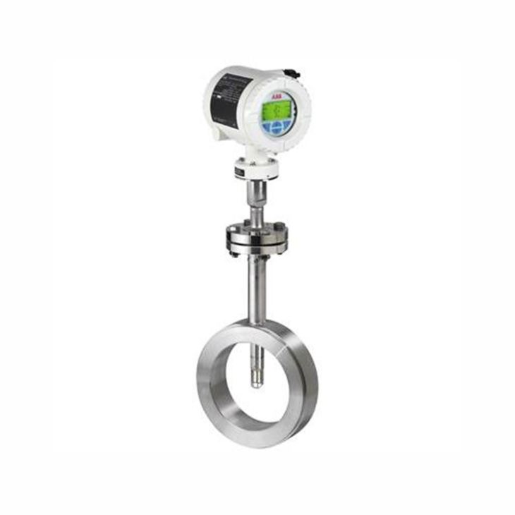
ABB FMT400 thermal mass flowmeter enjoys the features as follows:
1.1 Precise and dynamic direct mass flow measurement of gases for industrial standard applications.
1.2 High-grade thermal sensor elements
– superior long-term stability
– effective sensor element protection frame with flow conditioning properties
1.3 SmartSensor solution
– Meter intelligence located at the sensor
– all digital solution
– reduced wiring costs with industry standard connection cables
– long cable distances are possible
1.4 SensorApplicationMemory
– Plug and play electronics replacement
– Redundant data storage for maximum data security
1.5 ABB common electronic concept
– Through-the-glass operation
– Modular I/O Concept
– Multiple 32-bit processor structure
– full digital heating circuit control
– dynamic temperature compensation
1.6 ApplicationSelector
– Adaption of the characteristic application parameters on site
– choice between up to two applications (FMT430)
– choice between up to eight applications (FMT450)
– setup new applications without the need for recalibration (FMT450)
1.7 VeriMass onboard verification and diagnostics
– Fingerprint based SensorCheck to verify the integrity of the thermal sensor elements
– continuous health check of the meter
– parameter plausibility check
2. Compare Table of FMT430 and FMT450
Model | FMT430 | FMT450 |
Design | Integral mount design, remote mount design; Transmitter optionally available in single-compartment housing or dual-compartment housing | |
Measuring media | Gas (air ,methane, nitrogen, hydrogen, carbon dioxide, oxygen, natural gas, ammonia, helium, argon, propane, ethane, butane, ethene, biogas) and gas mixtures with known compositions | |
Measuring accuracy for gases Air, nitrogen | ± 1.2 % of Qm in the range of 10 ... 100% of the measuring range; ± 0.12 % of the QmaxDN possible in the nominal diameter in the range of 0 ... 10 % of the measuring range | ± 0.6 % of the measured value, ± 0.05% of the QmaxDN possible in the nominal diameter |
Other gases (optional process gas calibration) | – | ± 1.6 % of the measured value, ± 0.1 % of the QmaxDN possible in the nominal diameter |
Extended measuring range | No | Yes, optional |
Measuring medium temperature Tmedium | Standard: -25 ... 150 °C (-13 ... 302 °F) | Standard: -25 ... 150 °C (-13 ... 302 °F), optional: -25 ... 300 °C (-13 ... 572 °F) |
Ambient temperature Tambient | Standard: -20 ... 70 °C (-4 ... 158 °F), optional:-40 ... 70 °C (-40 ... 158 °F), -50 ... 70 °C (-58 ... 158 °F) | |
Sensor connection | Flange DN 25 – PN 40, threaded connection DN 11851, compression fitting | |
Wetted materials | Stainless steel, ceramic measuring element (other materials on request) | |
IP rating | In accordance with EN 60529: IP 65 / IP 67 | |
NEMA rating | In accordance with NEMA 4X | |
Approvals and certificates | ||
Explosion protection ATEX / IECEx | Further approvals | |
Explosion protection cFMus | Further approvals | |
Further approvals | Available on our website abb.com/flow or on request | |
Pipe components | ||
FMT091 – Wafer type design | In accordance with EN 1092-1 DN 40 ... 200, PN 40 In accordance with ASME B16.5 1 1/2 ... 8”, CL 150 ... 300 | |
FMT092 – Partial measuring section | Flange in accordance with EN 1092-1, DN 40 ... 100 (larger nominal diameters on request), PN 10 ... 40. Flange in accordance with ASME B16.5 1 1/2 ... 8”, CL 150 ... 300 Male thread DN 25 ... 80 R1 in. ... 3 in. | |
FMT094 – Weld-on adapter | For rectangular ducts or pipe diameters ≥ DN 100 (4 in.), PN 16 ... 40 | |
Wetted materials | Stainless steel, galvanized steel (other materials on request) | |
3. Measuring Range Table
Nominal diameter | Standard measuring range | Extended measuring range (only with FMT450) | ||
Qmax [kg/h] | Qmax [Nm3/h] | Qmax [kg/h] | Qmax [Nm3/h] | |
Devices with process connections in accordance with EN 1029-1 | ||||
DN 25 (1 in.) | 180 | 140 | 240 | 180 |
DN 40 (1 1/2 in.) | 450 | 350 | 590 | 450 |
DN 50 (2 in.) | 800 | 620 | 1050 | 820 |
DN 65 (2 1/2 in.) | 1400 | 1100 | 1750 | 1400 |
DN 80 (3 in.) | 1900 | 1500 | 2400 | 1900 |
DN 100 (4 in.) | 3200 | 2500 | 4100 | 3200 |
DN 125 (5 in.) | 4800 | 3800 | 6200 | 4800 |
DN 150 (6 in.) | 7000 | 5500 | 9000 | 7000 |
DN 200 (8 in.) | 12000 | 9300 | 15000 | 12000 |
Ø up to 3000 mm (118 in.) | 2500000 | 2000000 | 3200000 | 2500000 |
Device with process connections in accordance with ASME B16.5 | ||||
1in | 350 | 75 | 450 | 100 |
1 1/2 in. | 880 | 190 | 1100 | 250 |
2 in. | 1600 | 350 | 2000 | 450 |
3 in. | 3700 | 820 | 4900 | 1100 |
4 in. | 6400 | 1400 | 8400 | 1850 |
6 in. | 14500 | 3200 | 19000 | 4200 |
8 in | 25500 | 5600 | 33100 | 7300 |
Ø up to 3000 mm (118 in.) | 5500000 | 1200000 | 7100000 | 1600000 |
4. Basic Code Selection of FMT430
Main Code | Suffix Codes | Description | ||||||||
FMT430 | Always FMT430 | |||||||||
Explosion Protection Certification | Y0 | Without | ||||||||
Measuring Medium | C1 | Air or other clean gas (One gas component only) | ||||||||
C2 | Gas mixtures with max. 23.5 Vol% O2 (eg. Natural gas or Biogas) | |||||||||
P1 | Oxygen / gas mixtures > 23.5 Vol% O2, oil and grease-free, with O2 certificate (max. 150 °C / 302 °F) | |||||||||
H3 | Ammonia | |||||||||
Sensor Element Type / Temperature Range of Measuring Medium | A | Standard ceramic sensor / Standard range -25 ... 150 °C (-13 ... 302 °F) | ||||||||
Mounting Length / Flowmeter Sensor Material | 1 | 120 mm (4.7 in.) / AISI 316Ti SST (1.4571) (DN 25 ... DN 125 [1 ... 5 in.]) | ||||||||
2 | 263 mm (10.4 in.) / AISI 316Ti SST (1.4571) (DN 25 ... DN 350 [1 ... 14 in.]) | |||||||||
3 | 425 mm (17 in.) / AISI 316Ti SST (1.4571) (> DN 350 ... DN 700 [> 14 ... 28 in.]) | |||||||||
4 | 775 mm (31 in.) / AISI 316Ti SST (1.4571) (> DN 700 [> 28in.]) | |||||||||
Sensor Connection | D3 | Flange DN 25, nominal pressure 4 MPa (40 bar, 580 psi) | ||||||||
G2 | Compression fitting, stainless steel, nominal pressure 2 Mpa (20 bar, 290 psi) (-25 ... 140 °C (-13 ... 284 °F)) (> DN80) | |||||||||
F1 | Thread DIN 11851, nominal pressure 1.6 Mpa (16 bar, 232 psi) (-40 ... 140 °C (-40 ... 284 °F)) | |||||||||
Connection Design / Transmitter Housing Type / Transmitter Housing Material / Cable Glands | S1 | Integral / Single compartment / Aluminium / 2 x M20 x 1.5 | ||||||||
S2 | Integral / Single compartment / Aluminium / 2 x NPT 1/2 in. | |||||||||
D1 | Integral / Single compartment / Stainless Steel / 2 x M20 x 1.5 | |||||||||
D2 | Integral / Single compartment / Stainless Steel / 2 x NPT 1/2 in. | |||||||||
Y0 | Remote / Not specified (Remote TX or replacement Sensor) | |||||||||
Connection Design / Sensor Housing Type / Sensor Housing Material / Cable Glands | A1 | Remote / Single compartment / Aluminium / 1 x M20 x 1.5 | ||||||||
A2 | Remote / Single compartment / Aluminium / 1 x NPT 1/2 in. | |||||||||
U1 | Remote / Single compartment / Stainless Steel / 1 x M20 x 1.5 | |||||||||
U2 | Remote / Single compartment / Stainless Steel / 1 x NPT 1/2 in. | |||||||||
Y0 | Without | |||||||||
Outputs | G0 | Current output 1 (active or passive), digitial output 1 & 2 (passive), HART | ||||||||
G2 | Current output 1 (active), digitial output 1 & 2 (passive), current output 2 (passive), HART | |||||||||
G8 | Current output 1 (active or passive), digitial output 1 & 2 (passive), digital Input (passive), HART | |||||||||
Y0 | Without (Remote TX or replacement Sensor) | |||||||||
Power Supply | A | 100...240V AC, 50/60Hz | ||||||||
B | 24 V DC, +/- 20 % | |||||||||
Y | Without (Remote TX or replacement Sensor) | |||||||||
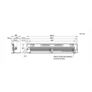
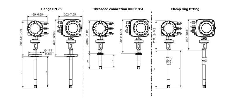
5. Dimensions of Flowmeter Sensor for Integral Mount Design

Copyright © Rostock Group Co.,Limited All Rights Reserved. Sitemap
 QR Code