1. General Introduction
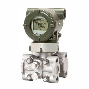
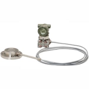
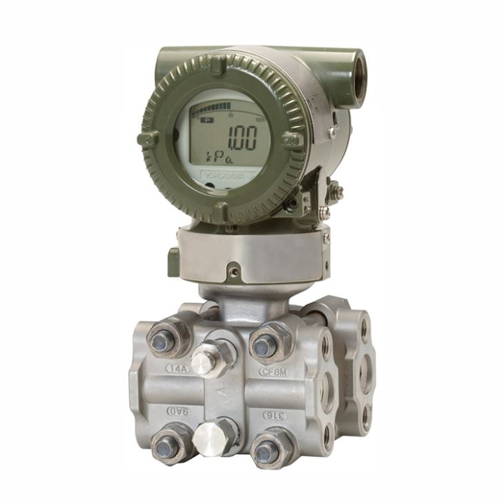
EJA120E differential pressure transmitter is a high performance draft range type specially for very low range differential pressure measurement, it specially for 0-1kpa applications. It supports 5 types of output signals. For output signal -D, it's based on brain protocol with 4 to 20 mA DC with digital communication; for output signal -J, it's based on Hart protocol with 4 to 20 mA DC with digital communication based on Hart 5/Hart7, Hart 7 is a low power consumption type which can be ordered for power economical plants application which need to specify during order stage; otherwise deem to Hart 7 automatically; for output signal -F, it's based on FOUNDATION Fieldbus protocol Digital communication; for output signal -G, it's based on PROFIBUS PA protocol Digital communication; for for output signal -Q, it's based on Hart 7 low power digital communication based on 1 to 5 V DC.
2. Measuring Span & Range limits
Measurement Span/Range | kPa | inH2O (/D1) | mbar (/D3) | mmH2O (/D4) | ||
E | Span | 0.1 to 1 | 0.4 to 4 | 1 to 10 | 10 to 100 | |
Range | -1 to 1 | -4 to 4 | -10 to 10 | -100 to 100 | ||
3. Wetted Parts Materials
Wetted parts | Cover flange and process connector | Capsule | Capsule gasket | Vent/Drain plug |
S | ASTM CF-8M | Hastelloy C-276 (Diaphragm) F316L SST, 316L SST (Others) | PTFE Teflon | 316 SST |
4. Model and suffix codes
Main Code | Suffix Codes | Description | |||||||||
EJA120E | Differential pressure transmitter | ||||||||||
Output signal | -D | 4 to 20 mA DC with digital communication (BRAIN protocol) | |||||||||
-J | 4 to 20 mA DC with digital communication (HART 5/HART 7 protocol) | ||||||||||
-F | Digital communication (FOUNDATION Fieldbus protocol) | ||||||||||
-G | Digital communication (PROFIBUS PA protocol) | ||||||||||
-Q | Low Power, 1 to 5 V DC with digital communication (HART 7 protocol) | ||||||||||
Measurement span (capsule) | F | 0.1 to 1 kPa (0.4 to 4 inH2O) | |||||||||
Wetted parts material | Refer to “Wetted Parts Material” Table | ||||||||||
Process connections | 0 | without process connector(Rc1/4 female on the cover flanges) | |||||||||
1 | with Rc1/4 female process connector | ||||||||||
2 | with Rc1/2 female process connector | ||||||||||
3 | with 1/4 NPT female process connector | ||||||||||
4 | with 1/2 NPT female process connector | ||||||||||
5 | without process connector (1/4 NPT female on the cover flanges) | ||||||||||
Bolts and nuts material | J | B7 carbon steel | |||||||||
G | 316L SST | ||||||||||
C | 660 SST | ||||||||||
Installation | -7 | Vertical piping, left side high pressure, and process connection downside | |||||||||
-8 | Horizontal piping and right side high pressure | ||||||||||
-9 | Horizontal piping and left side high pressure | ||||||||||
-B | Bottom Process Connection, left side high pressure | ||||||||||
-U | Universal flange | ||||||||||
Amplifier housing | 1 | Cast aluminum alloy | |||||||||
3 | Cast aluminum alloy with corrosion resistance properties | ||||||||||
2 | ASTM CF-8M stainless steel | ||||||||||
Electrical connection | 0 | G1/2 female, one electrical connection without blind plugs | |||||||||
2 | 1/2 NPT female, two electrical connections without blind plugs | ||||||||||
4 | M20 female, two electrical connections without blind plugs | ||||||||||
5 | G1/2 female, two electrical connections and a blind plug | ||||||||||
7 | 1/2 NPT female, two electrical connections and a blind plug | ||||||||||
9 | M20 female, two electrical connections and a blind plug | ||||||||||
A | G1/2 female, two electrical connections and a SUS316 blind plug | ||||||||||
C | 1/2 NPT female, two electrical connections and a SUS316 blind plug | ||||||||||
D | M20 female, two electrical connections and a SUS316 blind plug | ||||||||||
Integral indicator | D | Digital indicator | |||||||||
E | Digital indicator with the range setting switch (push button) | ||||||||||
N | None | ||||||||||
Mounting bracket | B | 304 SST 2-inch pipe mounting, flat type (for horizontal piping) | |||||||||
D | 304 SST 2-inch pipe mounting, L type (for vertical piping) | ||||||||||
J | 316 SST 2-inch pipe mounting, flat type (for horizontal piping) | ||||||||||
K | 316 SST 2-inch pipe mounting, L type (for vertical piping) | ||||||||||
M | 316 SST 2-inch pipe mounting (for bottom process connection type) | ||||||||||
N | None | ||||||||||
Optional codes | /Optional codes | ||||||||||
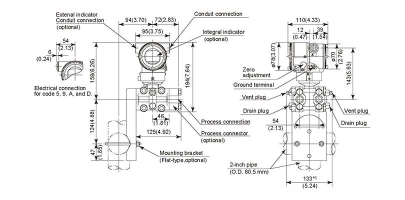
5. Mounting & Dimensions
◆ Vertical Impulse Piping Type Installation '7'
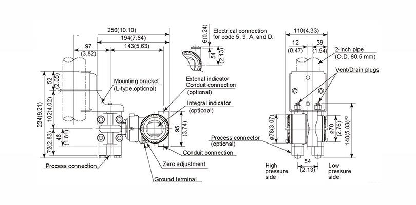
◆ Horizontal Impulse Piping Type (INSTALLATION CODE '9')
(For CODE '8', refer to the notes below.)
◆ Universal Flange (INSTALLATION CODE 'U')