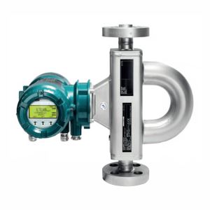
1.General Introduction
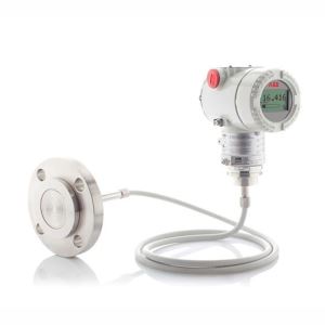
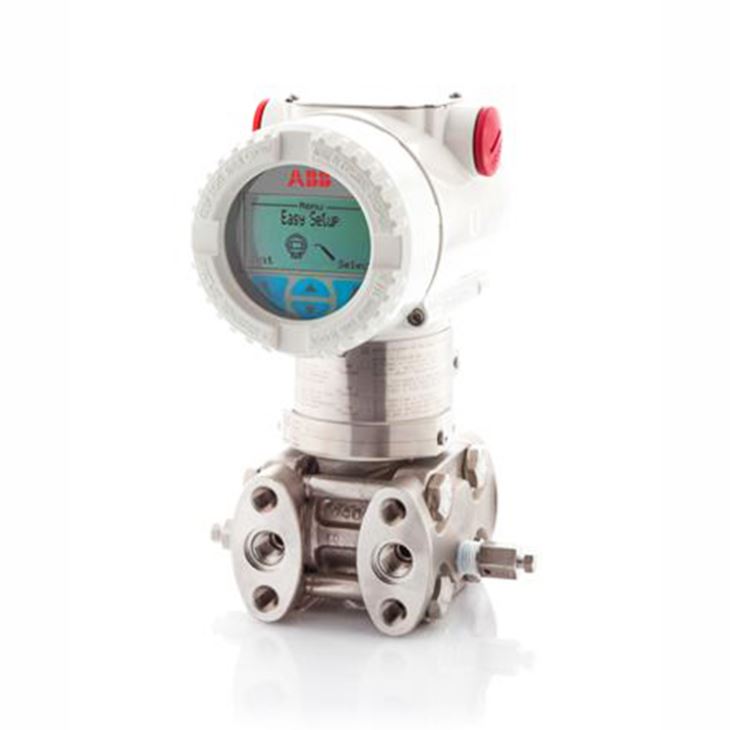
ABB 266DSH differential pressure transmitter is a traditional type for differential pressure measurement, measure range from -16Mpa to 16Mpa, maximum static pressure is up to 42Mpa and maximum turn down ratio up to 60:1, standard accuracy is 0.06%, maximum accuracy 0.04% is optional, meets SIL2,SIL3 safety applications as per IEC 61508 standard. Accordingly to customer requests, it can either be integrated to five way or three way M26 manifold, or remote connection to manifold via impulse line.
2.Measuring Span & Range Limits
Sensor Code | Lower Range Limit (LRL) | Upper Range Limit (URL) | Standard TD Ratio | Max. TD Ratio | Standard Static Pressure |
A | -1Kpa, -10mbar, -4inH2O | 1Kpa, 10mbar, 4inH2O | 4:1 | 20:1 | 2Mpa, 20bar, 290psi |
B | -4Kpa, -40mbar, -16inH2O | 4Kpa, 40mbar, 16inH2O | 10:1 | 20:1 | 7Mpa, 70bar, 1015psi |
E | -16Kpa, -160mbar, -64inH2O | 16Kpa, 160mbar, 64inH2O | 10:1 | 30:1 | 16Mpa, 160bar, 2320psi |
F | -40Kpa, -400mbar, -160inH2O | 40Kpa, 400mbar, 160inH2O | 10:1 | 100:1 | 42Mpa, 420bar, 6090psi |
H | -160Kpa, -1600mbar, -642inH2O | 160Kpa, 1600mbar, 642inH2O | 10:1 | 100:1 | 42Mpa, 420bar, 6090psi |
M | -600Kpa, -6bar, -87psi | 600Kpa, 6bar, 87psi | 10:1 | 100:1 | 42Mpa, 420bar, 6090psi |
P | -2400Kpa, -24bar, -348psi | 2400Kpa, 24bar, 348psi | 10:1 | 100:1 | 42Mpa, 420bar, 6090psi |
Q | -8000Kpa, -80bar, -1160psi | 8000Kpa, 80bar, 1160psi | 10:1 | 100:1 | 42Mpa, 420bar, 6090psi |
S | -16000Kpa, -160bar, -2320psi | 16000Kpa, 160bar, 2320psi | 10:1 | 100:1 | 42Mpa, 420bar, 6090psi |
3.Ambient & Process Temperature Llimits
Oil filling & sensor range | Ambient temperature limits | Process temperature limits |
Silicone oil for sensor F to S | -40 and 85℃ (-40 and 185℉) | -40 and 121℃ (-40 and 250℉) |
Silicone oil for sensor A to E | -25 and 85℃ (-13 and 185℉) | -25 and 121℃(-13 and 250℉) |
Inert (Galden) for sensor F to S | -20 and 85℃ (-4 and 185℉) | -20 and 100℃ (-4 and 212℉) |
Inert (Galden) for sensor E | -10 and 85℃ (14 and 185℉) | -10 and 100℃ (14 and 212℉) |
Inert (Halocarbon) for sensor F to S | -20 and 85℃ (-4 and 185℉) | -20 and 100℃ (-4 and 212℉) |
Inert (Halocarbon) for sensor E | -10 and 85℃ (14 and 185℉ | -10 and 100℃ (14 and 212℉) |
With LCD integral display | -40 and 85℃ (-40 and 185℉) | N/A |
With Viton gasket | N/A | -20 and 121℃ (-4 and 250℉) |
4.Basic Code Selection of 266DSH Differential Pressure Transmitter
Main Code | Suffix Codes | Description | ||||||
266DSH | Differential Pressure Transmitter with remote seal– BASE ACCURACY 0.06% | |||||||
SENSOR - Span limits | A | 0.05 and 1kpa,0.5 and 10mbar,0.2 and 4inH2o | ||||||
B | 0.2 and 4kpa,2 and 40mbar,0.8 and 16inH2o | |||||||
E | 0.8 and 16kpa,8 and 160mbar,3.2 and 64inH2o | |||||||
F | 0.67 and 40kpa,6.7 and 400mbar,2.67 and 160inH2o | |||||||
H | 2.67 and 160kpa,26.7 and 1600mbar,10.7 and 642inH2o | |||||||
M | 10 and 600kpa,0.1 and 6bar,1.45 and 87psi | |||||||
P | 40 and 2400kpa,0.4 and 24bar,5.8 and 348psi | |||||||
Q | 134 and 8000kpa,1.34 and 80bar,19.4 and 1160psi | |||||||
S | 267 and 16000kpa,2.67 and 160bar,38.7 and 2320psi | |||||||
Application | S | Differential measurement at standard static pressure | ||||||
H | Differential measurement at high static pressure | |||||||
P | Gauge measurement | |||||||
Diaphragm material , Fill fluid (wetted parts) | S | ANSI 316L SS, Silicone oil, NACE | ||||||
H | Hastelloy C276(on ANSI seat), Silicone oil, NACE | |||||||
K | Hastelloy C276, Silicone oil, NACE | |||||||
M | Monel 400, Silicone oil, NACE | |||||||
8 | ANSI 316L SS gold plated, Silicone oil, NACE | |||||||
T | Tantalum , Silicone oil, NACE | |||||||
A | ANSI 316L SS, Inert fluid - Galden, NACE | |||||||
F | Hastelloy C276, Inert fluid - Galden, NACE | |||||||
C | Monel 400, Inert fluid - Galden, NACE | |||||||
9 | ANSI 316L SS gold plated, Inert fluid - Galden, NACE | |||||||
D | Tantalum , Inert fluid - Galden, NACE | |||||||
L | ANSI 316L SS, Inert fluid - Halocarbon, NACE | |||||||
P | Hastelloy C276, Inert fluid - Halocarbon, NACE | |||||||
4 | Monel 400, Inert fluid - Halocarbon, NACE | |||||||
I | Monel 400, Inert fluid - Halocarbon, NACE | |||||||
5 | ANSI 316L SS gold plated, Inert fluid - Halocarbon, NACE | |||||||
Process flanges, adapters material and connection (wetted parts) | A | ANSI 316L SS horizontal connection, 1/4"-18NPT direct, NACE | ||||||
B | ANSI 316L SS horizontal connection, 1/2"-14NPT trough adaptor, NACE | |||||||
D | Hastelloy C276 horizontal connection, 1/4"-18NPT direct, NACE | |||||||
E | Hastelloy C276 horizontal connection, 1/2"-14NPT trough adaptor, NACE | |||||||
G | Monel 400 horizontal connection, 1/4"-18NPT direct, NACE | |||||||
H | Monel 400 horizontal connection, 1/2"-14NPT trough adaptor, NACE | |||||||
Q | ANSI 316L SS vertical connection, 1/4"-18NPT direct, NACE | |||||||
T | ANSI 316L SS vertical connection, 1/2"-14NPT trough adaptor, NACE | |||||||
M | Hastelloy C276 vertical connection, 1/4"-18NPT direct, NACE | |||||||
S | Hastelloy C276 vertical connection, 1/2"-14NPT trough adaptor, NACE | |||||||
U | Monel 400 vertical connection, 1/4"-18NPT direct, NACE | |||||||
V | Monel 400 vertical connection, 1/2"-14NPT trough adaptor, NACE | |||||||
P | PVDF insert on ANSI 316 SS flange side, 1/4"-18NPT direct | |||||||
Z | PVDF insert on ANSI 316 SS flange side, 1/2"-14NPT trough adaptor | |||||||
R | Flange mounted version | |||||||
Bolts/Gasket (wetted parts) | 1 | ANSI 316 SS, Viton, NACE | ||||||
2 | ANSI 316 SS, PTFE, NACE | |||||||
3 | ANSI 316 SS(MWP=16Mpa), Viton, NACE | |||||||
4 | ANSI 316 SS(MWP=16Mpa), PTFE, NACE | |||||||
3 | ANSI 316 SS(MWP=42Mpa), Viton, NACE | |||||||
4 | ANSI 316 SS(MWP=42Mpa), PTFE, NACE | |||||||
8 | Alloy(MWP=42Mpa), Viton, NACE | |||||||
9 | Alloy(MWP=42Mpa), PTFE, NACE | |||||||
N | ANSI 316 SS spring loaded(MWP=1Mpa) | |||||||
Housing material and electrical connection | A | Aluminum alloy ( barrel version), 1/2"-14NPT | ||||||
B | Aluminum alloy ( barrel version), M20*1.5 | |||||||
S | ANSI 316 SS ( barrel version), 1/2"-14NPT | |||||||
T | ANSI 316 SS ( barrel version), M20*1.5 | |||||||
J | Aluminum alloy ( DIN version) | |||||||
Output/Additional options | 7 | Hart 4-20mA, Standard function | ||||||
1 | Hart 4-20mA, Advanced function | |||||||
2 | Profibus PA | |||||||
3 | Foundation fieldbus | |||||||
8 | Hart 4-20mA, certified to IEC61058 | |||||||
9 | Wireless Hart | |||||||
Optional codes | /Optional codes | |||||||
5.Basic Code Selection of M26 Manifolds
Main Code | Suffix Codes | Description | |||||||||||||
M26 | Manifold model for 266 Pressure Transmitters | ||||||||||||||
Design | D | Manifold for DP Style transmitters | |||||||||||||
P | Manifold for P Style transmitters | ||||||||||||||
Revision | A | Revision A | |||||||||||||
Body configuration | S | Standard construction | |||||||||||||
V | For vertical-flange transmitter | ||||||||||||||
Valves | 2 | Two-valve manifold | |||||||||||||
3 | Three-valve manifold | ||||||||||||||
5 | Five-valve manifold | ||||||||||||||
Valve type | V | Standard | |||||||||||||
Material (wetted parts) | S | AISI 316L SS, NACE | |||||||||||||
H | Hastelloy C276, NACE | ||||||||||||||
M | Monel 400 | ||||||||||||||
N | Inconel 625 | ||||||||||||||
Packing material | P | PTFE | |||||||||||||
G | Graphoil | ||||||||||||||
Gasket material (wetted parts) | N | None | |||||||||||||
P | PTFE | ||||||||||||||
G | Graphoil | ||||||||||||||
Manifold process connection (INLET) | F | Threaded 1/2 in. - 14 NPT-female | |||||||||||||
M | Threaded 1/2 in. - 14 NPT-male | ||||||||||||||
Manifold transmitter connection (OUTLET) | 1 | Flanged outlet according to IEC61518/B | |||||||||||||
F | Threaded 1/2 in. - 14 NPT-female | ||||||||||||||
M | Threaded 1/2 in. - 14 NPT-male | ||||||||||||||
Rating | 6 | 413.7 bar (41.37MPa, 6000 psi) | |||||||||||||
1 | 690 bar (69MPa, 10000 psi) | ||||||||||||||
Transmitter fixing bolts | N | None | |||||||||||||
C | Carbon Steel | ||||||||||||||
S | Stainless Steel NACE compliant (MWP=21MPa, 210 bar, 3045 psi) | ||||||||||||||
Bracket kit | N | None | |||||||||||||
C | Carbon Steel | ||||||||||||||
S | Stainless Steel NACE compliant (MWP=21MPa, 210 bar, 3045 psi) | ||||||||||||||
Material traceability | 2 | Inspection certificate EN 10204–3.1 of process wetted parts | |||||||||||||
Optional codes | /Optional codes | ||||||||||||||
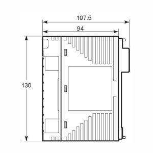
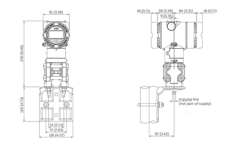
6. Typical Mounting & Dimensions for Barrel Housing Horizontal & Vertical Pipe Mounting 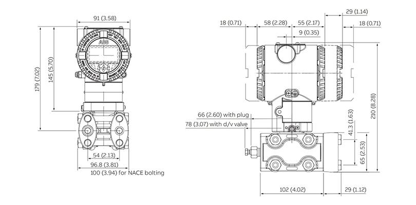
7.Typical Mounting & Dimensions for M26 5 Way Manifold for Horizontal & Vertical Flanges