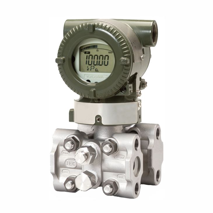
1. General Introduction
EJA310E Absolute Pressure Transmitter is a traditional type for absolute and vacuum measurement with traditional cover flanges and process connectors; measure range from 10kpa to 160bar, SS wetted material which mainly applicable for normal working cases.
2. Measuring Span & Range limits
Measurement | kPa abs | psi abs (/D1) | mbar abs (/D3) | mmHg abs (/D4) | |
L | Span | 0.67 to 10 | 0.2 to 2.95inHg | 6.7 to 100 | 5 to 75 |
Range | 0 to 10 | 0 to 2.95inHg | 0 to 100 | 0 to 75 | |
M | Span | 1.3 to 130 | 0.39 to 38inHg | 13 to 1300 | 9.8 to 970 |
Range | 0 to 130 | 0 to 38inHg | 0 to 1300 | 0 to 970 | |
A | Span | 0.03 to 3.5MPa | 4.3 to 500 | 0.3 to 35bar | 0.3 to 35kg/cm2 |
Range | 0 to 3.5MPa | 0 to 500 | 0 to 35 bar | 0 to 35kg/cm2 | |
B | Span | 0.14 to 16MPa | 20 to 2300 | 1.4 to 160bar | 1.4 to 160kg/cm2 |
Range | 0 to 16MPa | 0 to 2300 | -5 to 140 bar | 0 to 160kg/cm2 | |
3. Wetted Parts Materials
Wetted | Cover flange and process connector | Capsule | Capsule gasket | Vent/Drain plug |
S | ASTM CF-8M | Hastelloy C-276 (Diaphragm) F316L SST, 316L SST (Others) | Teflon-coated 316L SST | 316 SST |
4. Model and suffix codes
Main Code | Suffix Codes | Description | |||||||||
EJA310E | Absolute pressure transmitter | ||||||||||
Output signal | -D | 4 to 20 mA DC with digital communication (BRAIN protocol) | |||||||||
-J | 4 to 20 mA DC with digital communication (HART 5/HART 7 protocol) | ||||||||||
-F | Digital communication (FOUNDATION Fieldbus protocol) | ||||||||||
-G | Digital communication (PROFIBUS PA protocol) | ||||||||||
-Q | Low Power, 1 to 5 V DC with digital communication (HART 7 protocol) | ||||||||||
Measurement span (capsule) | L | 0.67 to 10kPa abs (0.2 to 2.95inHg abs) | |||||||||
M | 1.3 to 130kPa abs (0.39 to 38inHg abs) | ||||||||||
A | 0.03 to 3.5MPa abs (4.3 to 500psia) | ||||||||||
B | 0.14 to 16MPa abs (20 to 2300psia) | ||||||||||
Wetted parts material | S | Refer to “Wetted Parts Material” Table | |||||||||
Process connections | 0 | without process connector(Rc1/4 female on the cover flanges) | |||||||||
1 | with Rc1/4 female process connector | ||||||||||
2 | with Rc1/2 female process connector | ||||||||||
3 | with 1/4 NPT female process connector | ||||||||||
4 | with 1/2 NPT female process connector | ||||||||||
5 | without process connector (1/4 NPT female on the cover flanges) | ||||||||||
Bolts and nuts material | J | B7 carbon steel | |||||||||
G | 316L SST | ||||||||||
C | 660 SST | ||||||||||
Installation | -7 | Vertical piping, left side high pressure, and process connection downside | |||||||||
-8 | Horizontal piping and right side high pressure | ||||||||||
-9 | Horizontal piping and left side high pressure | ||||||||||
-B | Bottom Process Connection, left side high pressure | ||||||||||
-U | Universal flange | ||||||||||
Amplifier housing | 1 | Cast aluminum alloy | |||||||||
3 | Cast aluminum alloy with corrosion resistance properties | ||||||||||
2 | ASTM CF-8M stainless steel | ||||||||||
Electrical connection | 0 | G1/2 female, one electrical connection without blind plugs | |||||||||
2 | 1/2 NPT female, two electrical connections without blind plugs | ||||||||||
4 | M20 female, two electrical connections without blind plugs | ||||||||||
5 | G1/2 female, two electrical connections and a blind plug | ||||||||||
7 | 1/2 NPT female, two electrical connections and a blind plug | ||||||||||
9 | M20 female, two electrical connections and a blind plug | ||||||||||
A | G1/2 female, two electrical connections and a SUS316 blind plug | ||||||||||
C | 1/2 NPT female, two electrical connections and a SUS316 blind plug | ||||||||||
D | M20 female, two electrical connections and a SUS316 blind plug | ||||||||||
Integral indicator | D | Digital indicator | |||||||||
E | Digital indicator with the range setting switch (push button) | ||||||||||
N | None | ||||||||||
Mounting bracket | B | 304 SST 2-inch pipe mounting, flat type (for horizontal piping) | |||||||||
D | 304 SST 2-inch pipe mounting, L type (for vertical piping) | ||||||||||
J | 316 SST 2-inch pipe mounting, flat type (for horizontal piping) | ||||||||||
K | 316 SST 2-inch pipe mounting, L type (for vertical piping) | ||||||||||
M | 316 SST 2-inch pipe mounting (for bottom process connection type) | ||||||||||
N | None | ||||||||||
Optional codes | /Optional codes | ||||||||||
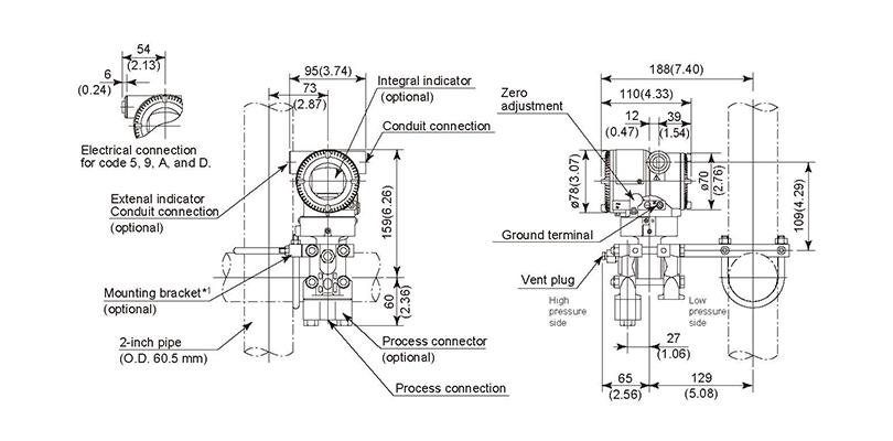
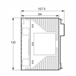
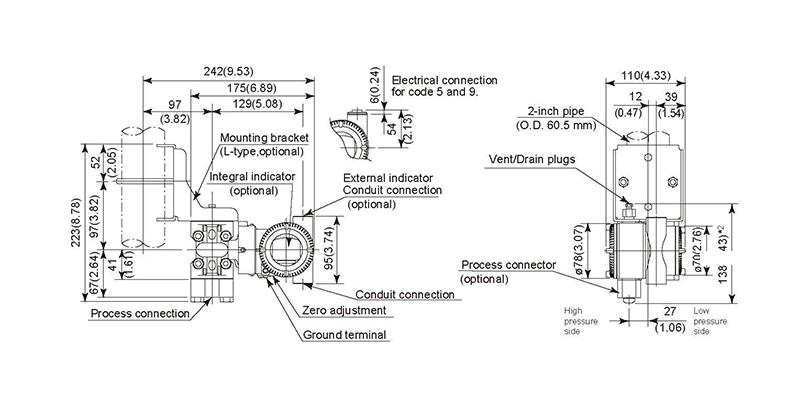
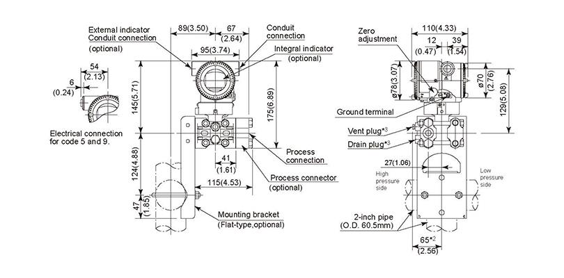
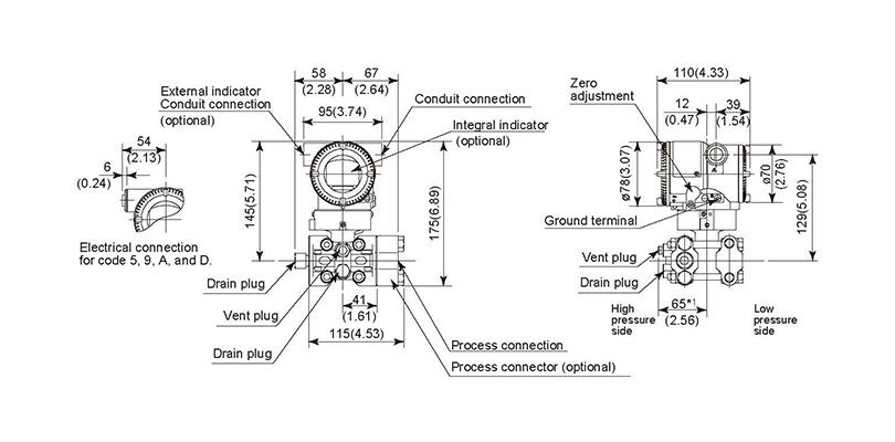
5. Mounting & Dimensions
◆ Vertical Impulse Piping Type Installation Code ‘7’
◆ Horizontal Impulse Piping Type Installation Code ‘9’
◆ Universal Flange Piping Type Installation Code ‘U’
◆ Bottom Process Connection Type Installation Code ‘B’