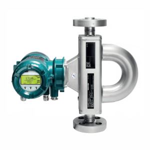
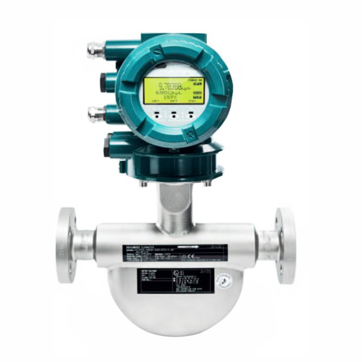
1. General Introduction
Prime Coriolis mass flow meter is for low flow applications, typical line sizes: DN15, DN25, DN40, DN50,DN65, DN80, 1/4", 1/2", 1", 1 1/2", 2" and maximum mass flow up to 80 t/h, It is the Ideal for a broad range of standard applications, this series is a flexible and cost effective solution for highly accurate flow and density measurements, features such as concentration measurement or the Tube Health Check function allow the meter to be adjusted to customer needs.
2. Measuring range limits
Meter size | Normal Mass Flow | Maximum mass flow | Normal Volume flow | Max Volume flow | Normal Temperature | Max. Temperature | Density |
Prime 25 | 1.6 t/h | 2.3 t/h | 1.6m3/h | 2.3 m3/h | -50 to150℃ | -70 to 200℃ | 0 to 5 kg/l |
Prime 40 | 4.7 t/h | 7 t/h | 4.7 m3/h | 7 m3/h | |||
Prime 50 | 20 t/h | 29 t/h | 20 m3/h | 29 m3/h | |||
Prime 80 | 51 t/h | 76 t/h | 51 m3/h | 76 m3/h |
3. Accuracy of liquids Measurement
Measured quantity | Accuracy for transmitters | ||
Essential | Ultimate | ||
Mass flow | Accuracy | 0.2 % of measured value | 0.1 % of measured value |
Repeatability | 0.1 % of measured value | 0.05 % of measured value | |
Volume flow | Accuracy | 0.45 % of measured value | 0.12 % of measured value |
Repeatability | 0.23 % of measured value | 0.06 % of measured value | |
Density | Accuracy | 4 g/l (0.25 lb/ft³) | 0.5 g/l (0.03 lb/ft³) |
Repeatability | 2 g/l (0.13 lb/ft³) | 0.3 g/l (0.02 lb/ft³) | |
Temperature | Accuracy | 1℃ (1.8℉) | 1℃ (1.8℉) |
4. Accuracy of gas Measurement
Measured quantity | Accuracy for transmitters | ||
Essential | Ultimate | ||
Mass flow | Accuracy | 0.75 % of measured value | 0.5 % of measured value |
Repeatability | 0.6 % of measured value | 0.4 % of measured value | |
Volume flow | Accuracy | 0.75 % of measured value | 0.5 % of measured value |
Repeatability | 0.6 % of measured value | 0.4 % of measured value | |
Temperature | Accuracy | 1℃ (1.8℉) | 1℃ (1.8℉) |
5. Model selection of Prime 25
Main Code | Suffix Codes | Description | |||||||||||||
RC | Always RC | ||||||||||||||
Transmitter | E | Essential (base function) | |||||||||||||
U | Ultimate (high function) | ||||||||||||||
Sensor | P | Prime | |||||||||||||
Meter size | 25 | Nominal mass flow : 1.6 t/h (59 lb/min), Maximum mass flow: 2.3 t/h (85 lb/min) | |||||||||||||
Material of wetted parts | S | stainless steel 1.4404/316L | |||||||||||||
Process connection size | 08 | ⅜" | |||||||||||||
15 | DN15, ½" | ||||||||||||||
20 | ¾" | ||||||||||||||
25 | DN25, 1" | ||||||||||||||
40 | DN40, 1½" | ||||||||||||||
Process connection type | BA1 | ASME flange class 150, suitable for ASME B16.5, raised face (RF) | |||||||||||||
BA2 | ASME flange class 300, suitable for ASME B16.5, raised face (RF) | ||||||||||||||
BA4 | ASME flange class 600, suitable for ASME B16.5, raised face (RF) | ||||||||||||||
CA4 | ASME flange class 600, suitable for ASME B16.5, ring joint (RJ) | ||||||||||||||
BD4 | EN flange PN 40, suitable for EN 1092-1 type B1, raised face (RF) | ||||||||||||||
ED4 | EN flange PN 40, suitable for EN 1092-1 type E, spigot | ||||||||||||||
FD4 | EN flange PN 40, suitable for EN 1092-1 type F, recess | ||||||||||||||
GD4 | EN flange PN 40, suitable for EN 1092-1 type D, groove | ||||||||||||||
BD6 | EN flange PN 100, suitable for EN 1092-1 type B1, raised face (RF) | ||||||||||||||
ED6 | EN flange PN 100, suitable for EN 1092-1 type E, spigot | ||||||||||||||
FD6 | EN flange PN 100, suitable for EN 1092-1 type F, recess | ||||||||||||||
GD6 | EN flange PN 100, suitable for EN 1092-1 type D, groove | ||||||||||||||
BJ1 | JIS flange 10K, JIS B 2220 | ||||||||||||||
BJ2 | JIS flange 20K, JIS B 2220 | ||||||||||||||
BP1 | JPI flange class 150 | ||||||||||||||
BP2 | JPI flange class 300 | ||||||||||||||
BP4 | JPI flange class 600 | ||||||||||||||
TG9 | Process connection with internal thread G | ||||||||||||||
TT9 | Process connection with internal thread NPT | ||||||||||||||
Sensor housing 0material | 0 | Stainless steel 1.4301/304, 1.4404/316L | |||||||||||||
1 | Stainless steel 1.4404/316L | ||||||||||||||
Process fluid temperature range | 0 | Standard: -50 to 150℃ (-58 to 302℉), remote type: -70 – 200 °C (-94 – 392 °F) | |||||||||||||
Mass flow and density accuracy | E7 | Liquid: 0.2 % maximum mass flow deviation, 4 g/l density deviation | |||||||||||||
E3 | Liquid: 0.2 % maximum mass flow deviation, 1 g/l density deviation | ||||||||||||||
E2 | Liquid: 0.2 % maximum mass flow deviation, 0.5 g/l density deviation | ||||||||||||||
D7 | Liquid: 0.15 % maximum mass flow deviation, 4 g/l density deviation | ||||||||||||||
D3 | Liquid: 0.15 % maximum mass flow deviation, 1 g/l density deviation | ||||||||||||||
D2 | Liquid: 0.15 % maximum mass flow deviation, 0.5 g/l density deviation | ||||||||||||||
C7 | Liquid: 0.1 % maximum mass flow deviation, 4 g/l density deviation | ||||||||||||||
C3 | Liquid: 0.1 % maximum mass flow deviation, 1 g/l density deviation | ||||||||||||||
C2 | Liquid: 0.1 % maximum mass flow deviation, 0.5 g/l density deviation | ||||||||||||||
70 | Gas: 0.75% maximum mass flow deviation | ||||||||||||||
50 | Gas: 0.5% maximum mass flow deviation | ||||||||||||||
Design and housing | 0 | Integral type with "urethane-cured polyester powder coating" coated aluminum transmitter housing | |||||||||||||
2 | Integral type with "corrosion protection coating" coated aluminum transmitter housing | ||||||||||||||
A | Remote type with "urethane-cured polyester powder coating" coated aluminum transmitter housing and standard neck sensor | ||||||||||||||
E | Remote type with "corrosion protection coating" coated aluminum transmitter housing and standard neck sensor | ||||||||||||||
J | Remote type stainless steel transmitter and standard neck sensor | ||||||||||||||
Ex approval | NN00 | None | |||||||||||||
KF21 | ATEX, explosion group IIC and IIIC | ||||||||||||||
KF22 | ATEX, explosion group IIB and IIIC | ||||||||||||||
SF21 | IECEx, explosion group IIC and IIIC | ||||||||||||||
SF22 | IECEx, explosion group IIB and IIIC | ||||||||||||||
GF21 | EAC Ex, explosion group IIC and IIIC | ||||||||||||||
GF22 | EAC Ex, explosion group IIB and IIIC | ||||||||||||||
FF11 | FM, groups A, B, C, D, E, F, G | ||||||||||||||
FF12 | FM, groups C, D, E, F, G | ||||||||||||||
UF21 | INMETRO, explosion group IIC and IIIC | ||||||||||||||
UF22 | INMETRO, explosion group IIB and IIIC | ||||||||||||||
NF21 | NEPSI, explosion group IIC and IIIC | ||||||||||||||
NF22 | NEPSI, explosion group IIB and IIIC | ||||||||||||||
PF21 | Korea Ex, explosion group IIC and IIIC | ||||||||||||||
PF22 | Korea Ex, explosion group IIB and IIIC | ||||||||||||||
Cable entries | 2 | ANSI ½" NPT | |||||||||||||
4 | ISO M20x1.5 | ||||||||||||||
Communication type and I/O | JA | active current output HART,1 passive pulse or status output | |||||||||||||
JB | 2 active current outputs one with HART,2 passive pulse or status outputs | ||||||||||||||
JC | 2 active current outputs one with HART,1 passive pulse or status output,1 voltage-free status input | ||||||||||||||
JD | 1 active current output HART,2 passive pulse or status outputs,1 passive status output | ||||||||||||||
JE | 1 active current output HART,2 passive pulse or status outputs,1 voltage-free status input | ||||||||||||||
JF | 1 active current output HART,1 passive pulse or status output,1 active pulse or status output with pull-up resistor,1 voltage-free status input | ||||||||||||||
JG | 1 active current output HART,1 passive pulse or status output,1 active pulse or status output,1 voltage-free status input | ||||||||||||||
JH | 1 active current output HART,1 passive pulse or status output,1 passive current output,1 active current input | ||||||||||||||
JJ | 1 active current output HART,2 passive pulse or status outputs,1 active current input | ||||||||||||||
JK | 1 active current output HART,1 passive pulse or status output,1 voltage-free status input,1 active current input | ||||||||||||||
JL | 1 active current output HART,1 passive pulse or status output,1 passive current output,1 passive current input | ||||||||||||||
JM | 1 active current output HART, 2 passive pulse or status outputs,1 passive current input | ||||||||||||||
JN | 1 active current output HART,1 passive pulse or status output,1 voltage-free status input,1 passive current input | ||||||||||||||
JP | 2 passive current outputs one with HART,1 passive pulse or status output | ||||||||||||||
JQ | 2 passive current outputs one with HART,2 passive pulse or status outputs | ||||||||||||||
JR | 2 passive current outputs one with HART,1 passive NAMUR pulse or status output | ||||||||||||||
JS | 2 passive current outputs one with HART,2 passive NAMUR pulse or status outputs | ||||||||||||||
M0 | Modbus output,1 passive pulse or status output | ||||||||||||||
M2 | Modbus output,1 passive pulse or status output,1 active current input | ||||||||||||||
M3 | Modbus output, 2 passive pulse or status outputs | ||||||||||||||
M4 | Modbus output,1 passive pulse or status output, 1 active pulse or status output | ||||||||||||||
M5 | Modbus output, 1 passive pulse or status output, 1 active pulse or status output with pull-up resistor | ||||||||||||||
M6 | Modbus output,1 passive pulse or status output, 1 active current output | ||||||||||||||
M7 | Modbus output, 1 passive pulse or status output, 1 passive current input | ||||||||||||||
Display | 0 | No display | |||||||||||||
1 | With display | ||||||||||||||
Optional codes | /Optional codes | ||||||||||||||
6. Model selection of Prime 40
Main Code | Suffix Codes | Description | |||||||||||||
RC | Always RC | ||||||||||||||
Transmitter | E | Essential (base function) | |||||||||||||
U | Ultimate (high function) | ||||||||||||||
Sensor | P | Prime | |||||||||||||
Meter size | 40 | Nominal mass flow : 4.7 t/h (170 lb/min), Maximum mass flow: 7 t/h (260 lb/min) | |||||||||||||
Material of wetted parts | S | stainless steel 1.4404/316L | |||||||||||||
15 | DN15, ½" | ||||||||||||||
20 | ¾" | ||||||||||||||
25 | DN25, 1" | ||||||||||||||
40 | DN40, 1½" | ||||||||||||||
Process connection type | BA1 | ASME flange class 150, suitable for ASME B16.5, raised face (RF) | |||||||||||||
BA2 | ASME flange class 300, suitable for ASME B16.5, raised face (RF) | ||||||||||||||
BA4 | ASME flange class 600, suitable for ASME B16.5, raised face (RF) | ||||||||||||||
CA4 | ASME flange class 600, suitable for ASME B16.5, ring joint (RJ) | ||||||||||||||
BD4 | EN flange PN 40, suitable for EN 1092-1 type B1, raised face (RF) | ||||||||||||||
ED4 | EN flange PN 40, suitable for EN 1092-1 type E, spigot | ||||||||||||||
FD4 | EN flange PN 40, suitable for EN 1092-1 type F, recess | ||||||||||||||
GD4 | EN flange PN 40, suitable for EN 1092-1 type D, groove | ||||||||||||||
BD6 | EN flange PN 100, suitable for EN 1092-1 type B1, raised face (RF) | ||||||||||||||
ED6 | EN flange PN 100, suitable for EN 1092-1 type E, spigot | ||||||||||||||
FD6 | EN flange PN 100, suitable for EN 1092-1 type F, recess | ||||||||||||||
GD6 | EN flange PN 100, suitable for EN 1092-1 type D, groove | ||||||||||||||
BJ1 | JIS flange 10K, JIS B 2220 | ||||||||||||||
BJ2 | JIS flange 20K, JIS B 2220 | ||||||||||||||
BP1 | JPI flange class 150 | ||||||||||||||
BP2 | JPI flange class 300 | ||||||||||||||
BP4 | JPI flange class 600 | ||||||||||||||
TG9 | Process connection with internal thread G | ||||||||||||||
TT9 | Process connection with internal thread NPT | ||||||||||||||
Sensor housing 0material | 0 | Stainless steel 1.4301/304, 1.4404/316L | |||||||||||||
1 | Stainless steel 1.4404/316L | ||||||||||||||
Process fluid temperature range | 0 | Standard: -50 to 150℃ (-58 to 302℉), remote type: -70 – 200 °C (-94 – 392 °F) | |||||||||||||
Mass flow and density accuracy | E7 | Liquid: 0.2 % maximum mass flow deviation, 4 g/l density deviation | |||||||||||||
E3 | Liquid: 0.2 % maximum mass flow deviation, 1 g/l density deviation | ||||||||||||||
E2 | Liquid: 0.2 % maximum mass flow deviation, 0.5 g/l density deviation | ||||||||||||||
D7 | Liquid: 0.15 % maximum mass flow deviation, 4 g/l density deviation | ||||||||||||||
D3 | Liquid: 0.15 % maximum mass flow deviation, 1 g/l density deviation | ||||||||||||||
D2 | Liquid: 0.15 % maximum mass flow deviation, 0.5 g/l density deviation | ||||||||||||||
C7 | Liquid: 0.1 % maximum mass flow deviation, 4 g/l density deviation | ||||||||||||||
C3 | Liquid: 0.1 % maximum mass flow deviation, 1 g/l density deviation | ||||||||||||||
C2 | Liquid: 0.1 % maximum mass flow deviation, 0.5 g/l density deviation | ||||||||||||||
70 | Gas: 0.75% maximum mass flow deviation | ||||||||||||||
50 | Gas: 0.5% maximum mass flow deviation | ||||||||||||||
Design and housing | 0 | Integral type with "urethane-cured polyester powder coating" coated aluminum transmitter housing | |||||||||||||
2 | Integral type with "corrosion protection coating" coated aluminum transmitter housing | ||||||||||||||
A | Remote type with "urethane-cured polyester powder coating" coated aluminum transmitter housing and standard neck sensor | ||||||||||||||
E | Remote type with "corrosion protection coating" coated aluminum transmitter housing and standard neck sensor | ||||||||||||||
J | Remote type stainless steel transmitter and standard neck sensor | ||||||||||||||
Ex approval | NN00 | None | |||||||||||||
KF21 | ATEX, explosion group IIC and IIIC | ||||||||||||||
KF22 | ATEX, explosion group IIB and IIIC | ||||||||||||||
SF21 | IECEx, explosion group IIC and IIIC | ||||||||||||||
SF22 | IECEx, explosion group IIB and IIIC | ||||||||||||||
GF21 | EAC Ex, explosion group IIC and IIIC | ||||||||||||||
GF22 | EAC Ex, explosion group IIB and IIIC | ||||||||||||||
FF11 | FM, groups A, B, C, D, E, F, G | ||||||||||||||
FF12 | FM, groups C, D, E, F, G | ||||||||||||||
UF21 | INMETRO, explosion group IIC and IIIC | ||||||||||||||
UF22 | INMETRO, explosion group IIB and IIIC | ||||||||||||||
NF21 | NEPSI, explosion group IIC and IIIC | ||||||||||||||
NF22 | NEPSI, explosion group IIB and IIIC | ||||||||||||||
PF21 | Korea Ex, explosion group IIC and IIIC | ||||||||||||||
PF22 | Korea Ex, explosion group IIB and IIIC | ||||||||||||||
Cable entries | 2 | ANSI ½" NPT | |||||||||||||
4 | ISO M20x1.5 | ||||||||||||||
Communication type and I/O | JA | active current output HART,1 passive pulse or status output | |||||||||||||
JB | 2 active current outputs one with HART,2 passive pulse or status outputs | ||||||||||||||
JC | 2 active current outputs one with HART,1 passive pulse or status output,1 voltage-free status input | ||||||||||||||
JD | 1 active current output HART,2 passive pulse or status outputs,1 passive status output | ||||||||||||||
JE | 1 active current output HART,2 passive pulse or status outputs,1 voltage-free status input | ||||||||||||||
JF | 1 active current output HART,1 passive pulse or status output,1 active pulse or status output with pull-up resistor,1 voltage-free status input | ||||||||||||||
JG | 1 active current output HART,1 passive pulse or status output,1 active pulse or status output,1 voltage-free status input | ||||||||||||||
JH | 1 active current output HART,1 passive pulse or status output,1 passive current output,1 active current input | ||||||||||||||
JJ | 1 active current output HART,2 passive pulse or status outputs,1 active current input | ||||||||||||||
JK | 1 active current output HART,1 passive pulse or status output,1 voltage-free status input,1 active current input | ||||||||||||||
JL | 1 active current output HART,1 passive pulse or status output,1 passive current output,1 passive current input | ||||||||||||||
JM | 1 active current output HART, 2 passive pulse or status outputs,1 passive current input | ||||||||||||||
JN | 1 active current output HART,1 passive pulse or status output,1 voltage-free status input,1 passive current input | ||||||||||||||
JP | 2 passive current outputs one with HART,1 passive pulse or status output | ||||||||||||||
JQ | 2 passive current outputs one with HART,2 passive pulse or status outputs | ||||||||||||||
JR | 2 passive current outputs one with HART,1 passive NAMUR pulse or status output | ||||||||||||||
JS | 2 passive current outputs one with HART,2 passive NAMUR pulse or status outputs | ||||||||||||||
M0 | Modbus output,1 passive pulse or status output | ||||||||||||||
M2 | Modbus output,1 passive pulse or status output,1 active current input | ||||||||||||||
M3 | Modbus output, 2 passive pulse or status outputs | ||||||||||||||
M4 | Modbus output,1 passive pulse or status output, 1 active pulse or status output | ||||||||||||||
M5 | Modbus output, 1 passive pulse or status output, 1 active pulse or status output with pull-up resistor | ||||||||||||||
M6 | Modbus output,1 passive pulse or status output, 1 active current output | ||||||||||||||
M7 | Modbus output, 1 passive pulse or status output, 1 passive current input | ||||||||||||||
Display | 0 | No display | |||||||||||||
1 | With display | ||||||||||||||
Optional codes | /Optional codes | ||||||||||||||
7. Model selection of Prime 50
Main Code | Suffix Codes | Description | |||||||||||||
RC | Always RC | ||||||||||||||
Transmitter | E | Essential (base function) | |||||||||||||
U | Ultimate (high function) | ||||||||||||||
Sensor | P | Prime | |||||||||||||
Meter size | 50 | Nominal mass flow : 20 t/h (730 lb/min), Maximum mass flow: 29 t/h (1100 lb/min) | |||||||||||||
Material of wetted parts | S | stainless steel 1.4404/316L | |||||||||||||
Process connection size | 25 | DN25, 1" | |||||||||||||
40 | DN40, 1½" | ||||||||||||||
50 | DN50, 2" | ||||||||||||||
Process connection type | BA1 | ASME flange class 150, suitable for ASME B16.5, raised face (RF) | |||||||||||||
BA2 | ASME flange class 300, suitable for ASME B16.5, raised face (RF) | ||||||||||||||
BA4 | ASME flange class 600, suitable for ASME B16.5, raised face (RF) | ||||||||||||||
CA4 | ASME flange class 600, suitable for ASME B16.5, ring joint (RJ) | ||||||||||||||
BD4 | EN flange PN 40, suitable for EN 1092-1 type B1, raised face (RF) | ||||||||||||||
ED4 | EN flange PN 40, suitable for EN 1092-1 type E, spigot | ||||||||||||||
FD4 | EN flange PN 40, suitable for EN 1092-1 type F, recess | ||||||||||||||
GD4 | EN flange PN 40, suitable for EN 1092-1 type D, groove | ||||||||||||||
BD6 | EN flange PN 100, suitable for EN 1092-1 type B1, raised face (RF) | ||||||||||||||
ED6 | EN flange PN 100, suitable for EN 1092-1 type E, spigot | ||||||||||||||
FD6 | EN flange PN 100, suitable for EN 1092-1 type F, recess | ||||||||||||||
GD6 | EN flange PN 100, suitable for EN 1092-1 type D, groove | ||||||||||||||
BJ1 | JIS flange 10K, JIS B 2220 | ||||||||||||||
BJ2 | JIS flange 20K, JIS B 2220 | ||||||||||||||
BP1 | JPI flange class 150 | ||||||||||||||
BP2 | JPI flange class 300 | ||||||||||||||
BP4 | JPI flange class 600 | ||||||||||||||
TG9 | Process connection with internal thread G | ||||||||||||||
TT9 | Process connection with internal thread NPT | ||||||||||||||
Sensor housing 0material | 0 | Stainless steel 1.4301/304, 1.4404/316L | |||||||||||||
1 | Stainless steel 1.4404/316L | ||||||||||||||
Process fluid temperature range | 0 | Standard: -50 to 150℃ (-58 to 302℉), remote type: -70 – 200 °C (-94 – 392 °F) | |||||||||||||
Mass flow and density accuracy | E7 | Liquid: 0.2 % maximum mass flow deviation, 4 g/l density deviation | |||||||||||||
E3 | Liquid: 0.2 % maximum mass flow deviation, 1 g/l density deviation | ||||||||||||||
E2 | Liquid: 0.2 % maximum mass flow deviation, 0.5 g/l density deviation | ||||||||||||||
D7 | Liquid: 0.15 % maximum mass flow deviation, 4 g/l density deviation | ||||||||||||||
D3 | Liquid: 0.15 % maximum mass flow deviation, 1 g/l density deviation | ||||||||||||||
D2 | Liquid: 0.15 % maximum mass flow deviation, 0.5 g/l density deviation | ||||||||||||||
C7 | Liquid: 0.1 % maximum mass flow deviation, 4 g/l density deviation | ||||||||||||||
C3 | Liquid: 0.1 % maximum mass flow deviation, 1 g/l density deviation | ||||||||||||||
C2 | Liquid: 0.1 % maximum mass flow deviation, 0.5 g/l density deviation | ||||||||||||||
70 | Gas: 0.75% maximum mass flow deviation | ||||||||||||||
50 | Gas: 0.5% maximum mass flow deviation | ||||||||||||||
Design and housing | 0 | Integral type with "urethane-cured polyester powder coating" coated aluminum transmitter housing | |||||||||||||
2 | Integral type with "corrosion protection coating" coated aluminum transmitter housing | ||||||||||||||
A | Remote type with "urethane-cured polyester powder coating" coated aluminum transmitter housing and standard neck sensor | ||||||||||||||
E | Remote type with "corrosion protection coating" coated aluminum transmitter housing and standard neck sensor | ||||||||||||||
J | Remote type stainless steel transmitter and standard neck sensor | ||||||||||||||
Ex approval | NN00 | None | |||||||||||||
KF21 | ATEX, explosion group IIC and IIIC | ||||||||||||||
KF22 | ATEX, explosion group IIB and IIIC | ||||||||||||||
SF21 | IECEx, explosion group IIC and IIIC | ||||||||||||||
SF22 | IECEx, explosion group IIB and IIIC | ||||||||||||||
GF21 | EAC Ex, explosion group IIC and IIIC | ||||||||||||||
GF22 | EAC Ex, explosion group IIB and IIIC | ||||||||||||||
FF11 | FM, groups A, B, C, D, E, F, G | ||||||||||||||
FF12 | FM, groups C, D, E, F, G | ||||||||||||||
UF21 | INMETRO, explosion group IIC and IIIC | ||||||||||||||
UF22 | INMETRO, explosion group IIB and IIIC | ||||||||||||||
NF21 | NEPSI, explosion group IIC and IIIC | ||||||||||||||
NF22 | NEPSI, explosion group IIB and IIIC | ||||||||||||||
PF21 | Korea Ex, explosion group IIC and IIIC | ||||||||||||||
PF22 | Korea Ex, explosion group IIB and IIIC | ||||||||||||||
Cable entries | 2 | ANSI ½" NPT | |||||||||||||
4 | ISO M20x1.5 | ||||||||||||||
Communication type and I/O | JA | active current output HART,1 passive pulse or status output | |||||||||||||
JB | 2 active current outputs one with HART,2 passive pulse or status outputs | ||||||||||||||
JC | 2 active current outputs one with HART,1 passive pulse or status output,1 voltage-free status input | ||||||||||||||
JD | 1 active current output HART,2 passive pulse or status outputs,1 passive status output | ||||||||||||||
JE | 1 active current output HART,2 passive pulse or status outputs,1 voltage-free status input | ||||||||||||||
JF | 1 active current output HART,1 passive pulse or status output,1 active pulse or status output with pull-up resistor,1 voltage-free status input | ||||||||||||||
JG | 1 active current output HART,1 passive pulse or status output,1 active pulse or status output,1 voltage-free status input | ||||||||||||||
JH | 1 active current output HART,1 passive pulse or status output,1 passive current output,1 active current input | ||||||||||||||
JJ | 1 active current output HART,2 passive pulse or status outputs,1 active current input | ||||||||||||||
JK | 1 active current output HART,1 passive pulse or status output,1 voltage-free status input,1 active current input | ||||||||||||||
JL | 1 active current output HART,1 passive pulse or status output,1 passive current output,1 passive current input | ||||||||||||||
JM | 1 active current output HART, 2 passive pulse or status outputs,1 passive current input | ||||||||||||||
JN | 1 active current output HART,1 passive pulse or status output,1 voltage-free status input,1 passive current input | ||||||||||||||
JP | 2 passive current outputs one with HART,1 passive pulse or status output | ||||||||||||||
JQ | 2 passive current outputs one with HART,2 passive pulse or status outputs | ||||||||||||||
JR | 2 passive current outputs one with HART,1 passive NAMUR pulse or status output | ||||||||||||||
JS | 2 passive current outputs one with HART,2 passive NAMUR pulse or status outputs | ||||||||||||||
M0 | Modbus output,1 passive pulse or status output | ||||||||||||||
M2 | Modbus output,1 passive pulse or status output,1 active current input | ||||||||||||||
M3 | Modbus output, 2 passive pulse or status outputs | ||||||||||||||
M4 | Modbus output,1 passive pulse or status output, 1 active pulse or status output | ||||||||||||||
M5 | Modbus output, 1 passive pulse or status output, 1 active pulse or status output with pull-up resistor | ||||||||||||||
M6 | Modbus output,1 passive pulse or status output, 1 active current output | ||||||||||||||
M7 | Modbus output, 1 passive pulse or status output, 1 passive current input | ||||||||||||||
Display | 0 | No display | |||||||||||||
1 | With display | ||||||||||||||
Optional codes | /Optional codes | ||||||||||||||
8. Model selection of Prime 80
Main Code | Suffix Codes | Description | |||||||||||||
RC | Always RC | ||||||||||||||
Transmitter | E | Essential (base function) | |||||||||||||
U | Ultimate (high function) | ||||||||||||||
Sensor | P | Prime | |||||||||||||
Meter size | 80 | Nominal mass flow : 51 t/h (1900 lb/min), Maximum mass flow: 76 t/h (2800 lb/min) | |||||||||||||
Material of wetted parts | S | stainless steel 1.4404/316L | |||||||||||||
Process connection size | 40 | DN40, 1½" | |||||||||||||
50 | DN50, 2" | ||||||||||||||
65 | 2½" | ||||||||||||||
80 | DN80, 3" | ||||||||||||||
Process connection type | BA1 | ASME flange class 150, suitable for ASME B16.5, raised face (RF) | |||||||||||||
BA2 | ASME flange class 300, suitable for ASME B16.5, raised face (RF) | ||||||||||||||
BA4 | ASME flange class 600, suitable for ASME B16.5, raised face (RF) | ||||||||||||||
CA4 | ASME flange class 600, suitable for ASME B16.5, ring joint (RJ) | ||||||||||||||
BD4 | EN flange PN 40, suitable for EN 1092-1 type B1, raised face (RF) | ||||||||||||||
ED4 | EN flange PN 40, suitable for EN 1092-1 type E, spigot | ||||||||||||||
FD4 | EN flange PN 40, suitable for EN 1092-1 type F, recess | ||||||||||||||
GD4 | EN flange PN 40, suitable for EN 1092-1 type D, groove | ||||||||||||||
BD6 | EN flange PN 100, suitable for EN 1092-1 type B1, raised face (RF) | ||||||||||||||
ED6 | EN flange PN 100, suitable for EN 1092-1 type E, spigot | ||||||||||||||
FD6 | EN flange PN 100, suitable for EN 1092-1 type F, recess | ||||||||||||||
GD6 | EN flange PN 100, suitable for EN 1092-1 type D, groove | ||||||||||||||
BJ1 | JIS flange 10K, JIS B 2220 | ||||||||||||||
BJ2 | JIS flange 20K, JIS B 2220 | ||||||||||||||
BP1 | JPI flange class 150 | ||||||||||||||
BP2 | JPI flange class 300 | ||||||||||||||
BP4 | JPI flange class 600 | ||||||||||||||
TG9 | Process connection with internal thread G | ||||||||||||||
TT9 | Process connection with internal thread NPT | ||||||||||||||
Sensor housing 0material | 0 | Stainless steel 1.4301/304, 1.4404/316L | |||||||||||||
1 | Stainless steel 1.4404/316L | ||||||||||||||
Process fluid temperature range | 0 | Standard: -50 to 150℃ (-58 to 302℉), remote type: -70 – 200 °C (-94 – 392 °F) | |||||||||||||
Mass flow and density accuracy | E7 | Liquid: 0.2 % maximum mass flow deviation, 4 g/l density deviation | |||||||||||||
E3 | Liquid: 0.2 % maximum mass flow deviation, 1 g/l density deviation | ||||||||||||||
E2 | Liquid: 0.2 % maximum mass flow deviation, 0.5 g/l density deviation | ||||||||||||||
D7 | Liquid: 0.15 % maximum mass flow deviation, 4 g/l density deviation | ||||||||||||||
D3 | Liquid: 0.15 % maximum mass flow deviation, 1 g/l density deviation | ||||||||||||||
D2 | Liquid: 0.15 % maximum mass flow deviation, 0.5 g/l density deviation | ||||||||||||||
C7 | Liquid: 0.1 % maximum mass flow deviation, 4 g/l density deviation | ||||||||||||||
C3 | Liquid: 0.1 % maximum mass flow deviation, 1 g/l density deviation | ||||||||||||||
C2 | Liquid: 0.1 % maximum mass flow deviation, 0.5 g/l density deviation | ||||||||||||||
70 | Gas: 0.75% maximum mass flow deviation | ||||||||||||||
50 | Gas: 0.5% maximum mass flow deviation | ||||||||||||||
Design and housing | 0 | Integral type with "urethane-cured polyester powder coating" coated aluminum transmitter housing | |||||||||||||
2 | Integral type with "corrosion protection coating" coated aluminum transmitter housing | ||||||||||||||
A | Remote type with "urethane-cured polyester powder coating" coated aluminum transmitter housing and standard neck sensor | ||||||||||||||
E | Remote type with "corrosion protection coating" coated aluminum transmitter housing and standard neck sensor | ||||||||||||||
J | Remote type stainless steel transmitter and standard neck sensor | ||||||||||||||
Ex approval | NN00 | None | |||||||||||||
KF21 | ATEX, explosion group IIC and IIIC | ||||||||||||||
KF22 | ATEX, explosion group IIB and IIIC | ||||||||||||||
SF21 | IECEx, explosion group IIC and IIIC | ||||||||||||||
SF22 | IECEx, explosion group IIB and IIIC | ||||||||||||||
GF21 | EAC Ex, explosion group IIC and IIIC | ||||||||||||||
GF22 | EAC Ex, explosion group IIB and IIIC | ||||||||||||||
FF11 | FM, groups A, B, C, D, E, F, G | ||||||||||||||
FF12 | FM, groups C, D, E, F, G | ||||||||||||||
UF21 | INMETRO, explosion group IIC and IIIC | ||||||||||||||
UF22 | INMETRO, explosion group IIB and IIIC | ||||||||||||||
NF21 | NEPSI, explosion group IIC and IIIC | ||||||||||||||
NF22 | NEPSI, explosion group IIB and IIIC | ||||||||||||||
PF21 | Korea Ex, explosion group IIC and IIIC | ||||||||||||||
PF22 | Korea Ex, explosion group IIB and IIIC | ||||||||||||||
Cable entries | 2 | ANSI ½" NPT | |||||||||||||
4 | ISO M20x1.5 | ||||||||||||||
Communication type and I/O | JA | active current output HART,1 passive pulse or status output | |||||||||||||
JB | 2 active current outputs one with HART,2 passive pulse or status outputs | ||||||||||||||
JC | 2 active current outputs one with HART,1 passive pulse or status output,1 voltage-free status input | ||||||||||||||
JD | 1 active current output HART,2 passive pulse or status outputs,1 passive status output | ||||||||||||||
JE | 1 active current output HART,2 passive pulse or status outputs,1 voltage-free status input | ||||||||||||||
JF | 1 active current output HART,1 passive pulse or status output,1 active pulse or status output with pull-up resistor,1 voltage-free status input | ||||||||||||||
JG | 1 active current output HART,1 passive pulse or status output,1 active pulse or status output,1 voltage-free status input | ||||||||||||||
JH | 1 active current output HART,1 passive pulse or status output,1 passive current output,1 active current input | ||||||||||||||
JJ | 1 active current output HART,2 passive pulse or status outputs,1 active current input | ||||||||||||||
JK | 1 active current output HART,1 passive pulse or status output,1 voltage-free status input,1 active current input | ||||||||||||||
JL | 1 active current output HART,1 passive pulse or status output,1 passive current output,1 passive current input | ||||||||||||||
JM | 1 active current output HART, 2 passive pulse or status outputs,1 passive current input | ||||||||||||||
JN | 1 active current output HART,1 passive pulse or status output,1 voltage-free status input,1 passive current input | ||||||||||||||
JP | 2 passive current outputs one with HART,1 passive pulse or status output | ||||||||||||||
JQ | 2 passive current outputs one with HART,2 passive pulse or status outputs | ||||||||||||||
JR | 2 passive current outputs one with HART,1 passive NAMUR pulse or status output | ||||||||||||||
JS | 2 passive current outputs one with HART,2 passive NAMUR pulse or status outputs | ||||||||||||||
M0 | Modbus output,1 passive pulse or status output | ||||||||||||||
M2 | Modbus output,1 passive pulse or status output,1 active current input | ||||||||||||||
M3 | Modbus output, 2 passive pulse or status outputs | ||||||||||||||
M4 | Modbus output,1 passive pulse or status output, 1 active pulse or status output | ||||||||||||||
M5 | Modbus output, 1 passive pulse or status output, 1 active pulse or status output with pull-up resistor | ||||||||||||||
M6 | Modbus output,1 passive pulse or status output, 1 active current output | ||||||||||||||
M7 | Modbus output, 1 passive pulse or status output, 1 passive current input | ||||||||||||||
Display | 0 | No display | |||||||||||||
1 | With display | ||||||||||||||
Optional codes | /Optional codes | ||||||||||||||
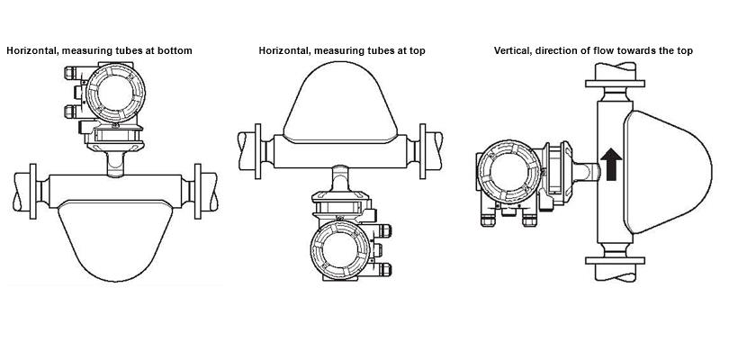
9. Location and position of installation