1. General introduction
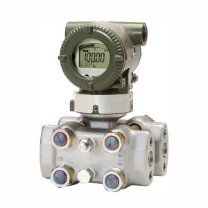
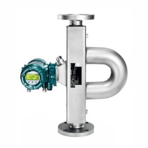
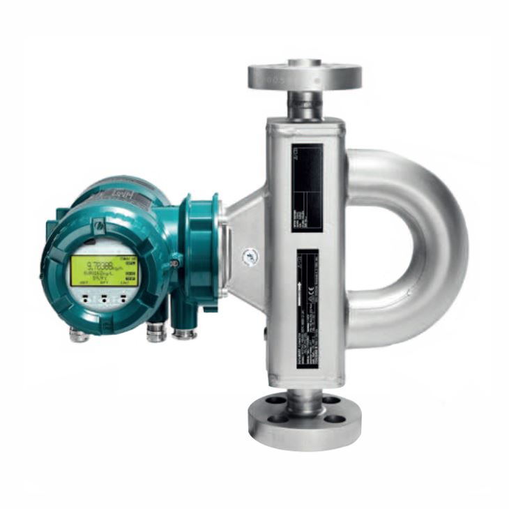
Intense Coriolis mass flow meter is for high pressure applications, typical line sizes: Typical line sizes: 1/2”, 1”, 2”and Maximum mass flow up to 50 t/h, has been designed to meet the highest safety requirements. Combined with advanced diagnosis such as the “Total Health Check” function, operation is always under secure control.
2. Measuring range limits
Meter size | Normal Mass Flow | Maximum mass flow | Normal Volume flow | Max Volume flow | Normal Temperature | Max. Temperature | Density |
Intense 34 | 3 t/h | 5 t/h | 3m3/h | 5 m3/h | -50 to150℃ | -70 to 150℃ | 0 to 5 kg/l |
Intense 36 | 10 t/h | 17 t/h | 10 m3/h | 17 m3/h | |||
Intense 38 | 32 t/h | 50 t/h | 32 m3/h | 50 m3/h |
3. Accuracy of liquids measurement
Measured quantity | Accuracy for transmitters | ||
Essential | Ultimate | ||
Mass flow | Accuracy | 0.15 % of measured value | 0.1 % of measured value |
Repeatability | 0.08 % of measured value | 0.05 % of measured value | |
Volume flow | Accuracy | 0.43 % of measured value | 0.12 % of measured value |
Repeatability | 0.22 % of measured value | 0.06 % of measured value | |
Density | Accuracy | 4 g/l (0.25 lb/ft³) | 0.5 g/l (0.03 lb/ft³) |
Repeatability | 2 g/l (0.13 lb/ft³) | 0.3 g/l (0.02 lb/ft³) | |
Temperature | Accuracy | 0.5℃ (0.9℉) | 0.5℃ (0.9℉) |
4. Accuracy of gas measurement
Measured quantity | Accuracy for transmitters | ||
Essential | Ultimate | ||
Mass flow | Accuracy | 0.15 % of measured value | 0.1 % of measured value |
Repeatability | 0.08 % of measured value | 0.05 % of measured value | |
Volume flow | Accuracy | 0.43 % of measured value | 0.12 % of measured value |
Repeatability | 0.22 % of measured value | 0.06 % of measured value | |
Density | Accuracy | 4 g/l (0.25 lb/ft³) | 0.5 g/l (0.03 lb/ft³) |
Repeatability | 2 g/l (0.13 lb/ft³) | 0.3 g/l (0.02 lb/ft³) | |
Temperature | Accuracy | 0.5℃ (0.9℉) | 0.5℃ (0.9℉) |
5. Model selection of Intense 34
Main Code | Suffix Codes | Description | |||||||||||||
RC | Always RC | ||||||||||||||
Transmitter | E | Essential (base function) | |||||||||||||
U | Ultimate (high function) | ||||||||||||||
Sensor | T | Intense | |||||||||||||
Meter size | 34 | Nominal mass flow : 3 t/h (110 lb/min), Maximum mass flow: 5 t/h (180 lb/min) | |||||||||||||
Material of wetted parts | S | Stainless steel 1.4404/316L | |||||||||||||
H | Ni alloy C-22/2.4602 | ||||||||||||||
Process connection size | 08 | ⅜" | |||||||||||||
15 | DN15, ½" | ||||||||||||||
20 | ¾" | ||||||||||||||
25 | DN25, 1" | ||||||||||||||
Process connection type | BA5 | ASME flange class 900, suitable for ASME B16.5, raised face (RF) | |||||||||||||
CA5 | ASME flange class 900, suitable for ASME B16.5, ring joint (RJ) | ||||||||||||||
BA6 | ASME flange class 1500, suitable for ASME B16.5, raised face (RF) | ||||||||||||||
CA6 | SME flange class 1500, suitable for ASME B16.5, ring joint (RJ) | ||||||||||||||
TG9 | Process connection with internal thread G | ||||||||||||||
TT9 | Process connection with internal thread NPT | ||||||||||||||
Sensor housing 0material | 0 | Stainless steel 1.4301/304, 1.4404/316L | |||||||||||||
1 | Stainless steel 1.4404/316L | ||||||||||||||
Process fluid temperature range | 0 | Standard integrate: -50 to 150℃ (-58 to 302℉), remote type: -70 to 200 °C (-94 – 392 °F) | |||||||||||||
Mass flow and density accuracy | E7 | Liquid: 0.2 % maximum mass flow deviation, 4 g/l density deviation | |||||||||||||
D7 | Liquid: 0.15 % maximum mass flow deviation, 4 g/l density deviation | ||||||||||||||
C3 | Liquid: 0.1 % maximum mass flow deviation, 1 g/l density deviation | ||||||||||||||
C2 | Liquid: 0.1 % maximum mass flow deviation, 0.5 g/l density deviation | ||||||||||||||
70 | Gas: 0.75% maximum mass flow deviation | ||||||||||||||
50 | Gas: 0.5% maximum mass flow deviation | ||||||||||||||
Design and housing | 0 | Integral type with "urethane-cured polyester powder coating" coated aluminum transmitter housing | |||||||||||||
2 | Integral type with "corrosion protection coating" coated aluminum transmitter housing | ||||||||||||||
A | Remote type with "urethane-cured polyester powder coating" coated aluminum transmitter housing and standard neck sensor | ||||||||||||||
B | Remote type with "urethane-cured polyester powder coating" coated aluminum transmitter housing and long neck sensor | ||||||||||||||
E | Remote type with "corrosion protection coating" coated aluminum transmitter housing and standard neck sensor | ||||||||||||||
F | Remote type with "corrosion protection coating" coated aluminum transmitter housing and long neck sensor | ||||||||||||||
J | Remote type stainless steel transmitter and standard neck sensor | ||||||||||||||
K | Remote type stainless steel transmitter and long neck sensor | ||||||||||||||
Ex approval | NN00 | None | |||||||||||||
KF21 | ATEX, explosion group IIC and IIIC | ||||||||||||||
KF22 | ATEX, explosion group IIB and IIIC | ||||||||||||||
SF21 | IECEx, explosion group IIC and IIIC | ||||||||||||||
SF22 | IECEx, explosion group IIB and IIIC | ||||||||||||||
GF21 | EAC Ex, explosion group IIC and IIIC | ||||||||||||||
GF22 | EAC Ex, explosion group IIB and IIIC | ||||||||||||||
FF11 | FM, groups A, B, C, D, E, F, G | ||||||||||||||
FF12 | FM, groups C, D, E, F, G | ||||||||||||||
UF21 | INMETRO, explosion group IIC and IIIC | ||||||||||||||
UF22 | INMETRO, explosion group IIB and IIIC | ||||||||||||||
NF21 | NEPSI, explosion group IIC and IIIC | ||||||||||||||
NF22 | NEPSI, explosion group IIB and IIIC | ||||||||||||||
PF21 | Korea Ex, explosion group IIC and IIIC | ||||||||||||||
PF22 | Korea Ex, explosion group IIB and IIIC | ||||||||||||||
Cable entries | 2 | ANSI ½" NPT | |||||||||||||
4 | ISO M20x1.5 | ||||||||||||||
Communication type and I/O | JA | active current output HART,1 passive pulse or status output | |||||||||||||
JB | 2 active current outputs one with HART,2 passive pulse or status outputs | ||||||||||||||
JC | 2 active current outputs one with HART,1 passive pulse or status output,1 voltage-free status input | ||||||||||||||
JD | 1 active current output HART,2 passive pulse or status outputs,1 passive status output | ||||||||||||||
JE | 1 active current output HART,2 passive pulse or status outputs,1 voltage-free status input | ||||||||||||||
JF | 1 active current output HART,1 passive pulse or status output,1 active pulse or status output with pull-up resistor,1 voltage-free status input | ||||||||||||||
JG | 1 active current output HART,1 passive pulse or status output,1 active pulse or status output,1 voltage-free status input | ||||||||||||||
JH | 1 active current output HART,1 passive pulse or status output,1 passive current output,1 active current input | ||||||||||||||
JJ | 1 active current output HART,2 passive pulse or status outputs,1 active current input | ||||||||||||||
JK | 1 active current output HART,1 passive pulse or status output,1 voltage-free status input,1 active current input | ||||||||||||||
JL | 1 active current output HART,1 passive pulse or status output,1 passive current output,1 passive current input | ||||||||||||||
JM | 1 active current output HART, 2 passive pulse or status outputs,1 passive current input | ||||||||||||||
JN | 1 active current output HART,1 passive pulse or status output,1 voltage-free status input,1 passive current input | ||||||||||||||
JP | 2 passive current outputs one with HART,1 passive pulse or status output | ||||||||||||||
JQ | 2 passive current outputs one with HART,2 passive pulse or status outputs | ||||||||||||||
JR | 2 passive current outputs one with HART,1 passive NAMUR pulse or status output | ||||||||||||||
JS | 2 passive current outputs one with HART,2 passive NAMUR pulse or status outputs | ||||||||||||||
M0 | Modbus output,1 passive pulse or status output | ||||||||||||||
M2 | Modbus output,1 passive pulse or status output,1 active current input | ||||||||||||||
M3 | Modbus output, 2 passive pulse or status outputs | ||||||||||||||
M4 | Modbus output,1 passive pulse or status output, 1 active pulse or status output | ||||||||||||||
M5 | Modbus output, 1 passive pulse or status output, 1 active pulse or status output with pull-up resistor | ||||||||||||||
M6 | Modbus output,1 passive pulse or status output, 1 active current output | ||||||||||||||
M7 | Modbus output, 1 passive pulse or status output, 1 passive current input | ||||||||||||||
Display | 0 | No display | |||||||||||||
1 | With display | ||||||||||||||
Optional codes | /Optional codes | ||||||||||||||
6. Model selection of Intense 36
Main Code | Suffix Codes | Description | |||||||||||||
RC | Always RC | ||||||||||||||
Transmitter | E | Essential (base function) | |||||||||||||
U | Ultimate (high function) | ||||||||||||||
Sensor | T | Intense | |||||||||||||
Meter size | 36 | Nominal mass flow : 10 t/h (370 lb/min), Maximum mass flow: 17 t/h (620 lb/min) | |||||||||||||
Material of wetted parts | S | Stainless steel 1.4404/316L | |||||||||||||
H | Ni alloy C-22/2.4602 | ||||||||||||||
25 | DN25, 1" | ||||||||||||||
50 | DN50, 2" | ||||||||||||||
Process connection type | BA5 | ASME flange class 900, suitable for ASME B16.5, raised face (RF) | |||||||||||||
CA5 | ASME flange class 900, suitable for ASME B16.5, ring joint (RJ) | ||||||||||||||
Sensor housing 0material | 0 | Stainless steel 1.4301/304, 1.4404/316L | |||||||||||||
1 | Stainless steel 1.4404/316L | ||||||||||||||
Process fluid temperature range | 0 | Standard integrate: -50 to 150℃ (-58 to 302℉), remote type: -70 to 200 °C (-94 – 392 °F) | |||||||||||||
Mass flow and density accuracy | E7 | Liquid: 0.2 % maximum mass flow deviation, 4 g/l density deviation | |||||||||||||
D7 | Liquid: 0.15 % maximum mass flow deviation, 4 g/l density deviation | ||||||||||||||
C3 | Liquid: 0.1 % maximum mass flow deviation, 1 g/l density deviation | ||||||||||||||
C2 | Liquid: 0.1 % maximum mass flow deviation, 0.5 g/l density deviation | ||||||||||||||
70 | Gas: 0.75% maximum mass flow deviation | ||||||||||||||
50 | Gas: 0.5% maximum mass flow deviation | ||||||||||||||
Design and housing | 0 | Integral type with "urethane-cured polyester powder coating" coated aluminum transmitter housing | |||||||||||||
2 | Integral type with "corrosion protection coating" coated aluminum transmitter housing | ||||||||||||||
A | Remote type with "urethane-cured polyester powder coating" coated aluminum transmitter housing and standard neck sensor | ||||||||||||||
B | Remote type with "urethane-cured polyester powder coating" coated aluminum transmitter housing and long neck sensor | ||||||||||||||
E | Remote type with "corrosion protection coating" coated aluminum transmitter housing and standard neck sensor | ||||||||||||||
F | Remote type with "corrosion protection coating" coated aluminum transmitter housing and long neck sensor | ||||||||||||||
J | Remote type stainless steel transmitter and standard neck sensor | ||||||||||||||
K | Remote type stainless steel transmitter and long neck sensor | ||||||||||||||
Ex approval | NN00 | None | |||||||||||||
KF21 | ATEX, explosion group IIC and IIIC | ||||||||||||||
KF22 | ATEX, explosion group IIB and IIIC | ||||||||||||||
SF21 | IECEx, explosion group IIC and IIIC | ||||||||||||||
SF22 | IECEx, explosion group IIB and IIIC | ||||||||||||||
GF21 | EAC Ex, explosion group IIC and IIIC | ||||||||||||||
GF22 | EAC Ex, explosion group IIB and IIIC | ||||||||||||||
FF11 | FM, groups A, B, C, D, E, F, G | ||||||||||||||
FF12 | FM, groups C, D, E, F, G | ||||||||||||||
UF21 | INMETRO, explosion group IIC and IIIC | ||||||||||||||
UF22 | INMETRO, explosion group IIB and IIIC | ||||||||||||||
NF21 | NEPSI, explosion group IIC and IIIC | ||||||||||||||
NF22 | NEPSI, explosion group IIB and IIIC | ||||||||||||||
PF21 | Korea Ex, explosion group IIC and IIIC | ||||||||||||||
PF22 | Korea Ex, explosion group IIB and IIIC | ||||||||||||||
Cable entries | 2 | ANSI ½" NPT | |||||||||||||
4 | ISO M20x1.5 | ||||||||||||||
Communication type and I/O | JA | active current output HART,1 passive pulse or status output | |||||||||||||
JB | 2 active current outputs one with HART,2 passive pulse or status outputs | ||||||||||||||
JC | 2 active current outputs one with HART,1 passive pulse or status output,1 voltage-free status input | ||||||||||||||
JD | 1 active current output HART,2 passive pulse or status outputs,1 passive status output | ||||||||||||||
JE | 1 active current output HART,2 passive pulse or status outputs,1 voltage-free status input | ||||||||||||||
JF | 1 active current output HART,1 passive pulse or status output,1 active pulse or status output with pull-up resistor,1 voltage-free status input | ||||||||||||||
JG | 1 active current output HART,1 passive pulse or status output,1 active pulse or status output,1 voltage-free status input | ||||||||||||||
JH | 1 active current output HART,1 passive pulse or status output,1 passive current output,1 active current input | ||||||||||||||
JJ | 1 active current output HART,2 passive pulse or status outputs,1 active current input | ||||||||||||||
JK | 1 active current output HART,1 passive pulse or status output,1 voltage-free status input,1 active current input | ||||||||||||||
JL | 1 active current output HART,1 passive pulse or status output,1 passive current output,1 passive current input | ||||||||||||||
JM | 1 active current output HART, 2 passive pulse or status outputs,1 passive current input | ||||||||||||||
JN | 1 active current output HART,1 passive pulse or status output,1 voltage-free status input,1 passive current input | ||||||||||||||
JP | 2 passive current outputs one with HART,1 passive pulse or status output | ||||||||||||||
JQ | 2 passive current outputs one with HART,2 passive pulse or status outputs | ||||||||||||||
JR | 2 passive current outputs one with HART,1 passive NAMUR pulse or status output | ||||||||||||||
JS | 2 passive current outputs one with HART,2 passive NAMUR pulse or status outputs | ||||||||||||||
M0 | Modbus output,1 passive pulse or status output | ||||||||||||||
M2 | Modbus output,1 passive pulse or status output,1 active current input | ||||||||||||||
M3 | Modbus output, 2 passive pulse or status outputs | ||||||||||||||
M4 | Modbus output,1 passive pulse or status output, 1 active pulse or status output | ||||||||||||||
M5 | Modbus output, 1 passive pulse or status output, 1 active pulse or status output with pull-up resistor | ||||||||||||||
M6 | Modbus output,1 passive pulse or status output, 1 active current output | ||||||||||||||
M7 | Modbus output, 1 passive pulse or status output, 1 passive current input | ||||||||||||||
Display | 0 | No display | |||||||||||||
1 | With display | ||||||||||||||
Optional codes | /Optional codes | ||||||||||||||
7. Model selection of Intense 38
Main Code | Suffix Codes | Description | |||||||||||||
RC | Always RC | ||||||||||||||
Transmitter | E | Essential (base function) | |||||||||||||
U | Ultimate (high function) | ||||||||||||||
Sensor | T | Intense | |||||||||||||
Meter size | 38 | Nominal mass flow : 32 t/h (1200 lb/min), Maximum mass flow: 50 t/h (1800 lb/min) | |||||||||||||
Material of wetted parts | S | Stainless steel 1.4404/316L | |||||||||||||
50 | DN50, 2" | ||||||||||||||
Process connection type | BA5 | ASME flange class 900, suitable for ASME B16.5, raised face (RF) | |||||||||||||
CA5 | ASME flange class 900, suitable for ASME B16.5, ring joint (RJ) | ||||||||||||||
Sensor housing 0material | 0 | Stainless steel 1.4301/304, 1.4404/316L | |||||||||||||
1 | Stainless steel 1.4404/316L | ||||||||||||||
Process fluid temperature range | 0 | Standard integrate: -50 to 150℃ (-58 to 302℉), remote type: -70 to 200 °C (-94 – 392 °F) | |||||||||||||
Mass flow and density accuracy | E7 | Liquid: 0.2 % maximum mass flow deviation, 4 g/l density deviation | |||||||||||||
D7 | Liquid: 0.15 % maximum mass flow deviation, 4 g/l density deviation | ||||||||||||||
C3 | Liquid: 0.1 % maximum mass flow deviation, 1 g/l density deviation | ||||||||||||||
C2 | Liquid: 0.1 % maximum mass flow deviation, 0.5 g/l density deviation | ||||||||||||||
70 | Gas: 0.75% maximum mass flow deviation | ||||||||||||||
50 | Gas: 0.5% maximum mass flow deviation | ||||||||||||||
Design and housing | 0 | Integral type with "urethane-cured polyester powder coating" coated aluminum transmitter housing | |||||||||||||
2 | Integral type with "corrosion protection coating" coated aluminum transmitter housing | ||||||||||||||
A | Remote type with "urethane-cured polyester powder coating" coated aluminum transmitter housing and standard neck sensor | ||||||||||||||
B | Remote type with "urethane-cured polyester powder coating" coated aluminum transmitter housing and long neck sensor | ||||||||||||||
E | Remote type with "corrosion protection coating" coated aluminum transmitter housing and standard neck sensor | ||||||||||||||
F | Remote type with "corrosion protection coating" coated aluminum transmitter housing and long neck sensor | ||||||||||||||
J | Remote type stainless steel transmitter and standard neck sensor | ||||||||||||||
K | Remote type stainless steel transmitter and long neck sensor | ||||||||||||||
Ex approval | NN00 | None | |||||||||||||
KF21 | ATEX, explosion group IIC and IIIC | ||||||||||||||
KF22 | ATEX, explosion group IIB and IIIC | ||||||||||||||
SF21 | IECEx, explosion group IIC and IIIC | ||||||||||||||
SF22 | IECEx, explosion group IIB and IIIC | ||||||||||||||
GF21 | EAC Ex, explosion group IIC and IIIC | ||||||||||||||
GF22 | EAC Ex, explosion group IIB and IIIC | ||||||||||||||
FF11 | FM, groups A, B, C, D, E, F, G | ||||||||||||||
FF12 | FM, groups C, D, E, F, G | ||||||||||||||
UF21 | INMETRO, explosion group IIC and IIIC | ||||||||||||||
UF22 | INMETRO, explosion group IIB and IIIC | ||||||||||||||
NF21 | NEPSI, explosion group IIC and IIIC | ||||||||||||||
NF22 | NEPSI, explosion group IIB and IIIC | ||||||||||||||
PF21 | Korea Ex, explosion group IIC and IIIC | ||||||||||||||
PF22 | Korea Ex, explosion group IIB and IIIC | ||||||||||||||
Cable entries | 2 | ANSI ½" NPT | |||||||||||||
4 | ISO M20x1.5 | ||||||||||||||
Communication type and I/O | JA | active current output HART,1 passive pulse or status output | |||||||||||||
JB | 2 active current outputs one with HART,2 passive pulse or status outputs | ||||||||||||||
JC | 2 active current outputs one with HART,1 passive pulse or status output,1 voltage-free status input | ||||||||||||||
JD | 1 active current output HART,2 passive pulse or status outputs,1 passive status output | ||||||||||||||
JE | 1 active current output HART,2 passive pulse or status outputs,1 voltage-free status input | ||||||||||||||
JF | 1 active current output HART,1 passive pulse or status output,1 active pulse or status output with pull-up resistor,1 voltage-free status input | ||||||||||||||
JG | 1 active current output HART,1 passive pulse or status output,1 active pulse or status output,1 voltage-free status input | ||||||||||||||
JH | 1 active current output HART,1 passive pulse or status output,1 passive current output,1 active current input | ||||||||||||||
JJ | 1 active current output HART,2 passive pulse or status outputs,1 active current input | ||||||||||||||
JK | 1 active current output HART,1 passive pulse or status output,1 voltage-free status input,1 active current input | ||||||||||||||
JL | 1 active current output HART,1 passive pulse or status output,1 passive current output,1 passive current input | ||||||||||||||
JM | 1 active current output HART, 2 passive pulse or status outputs,1 passive current input | ||||||||||||||
JN | 1 active current output HART,1 passive pulse or status output,1 voltage-free status input,1 passive current input | ||||||||||||||
JP | 2 passive current outputs one with HART,1 passive pulse or status output | ||||||||||||||
JQ | 2 passive current outputs one with HART,2 passive pulse or status outputs | ||||||||||||||
JR | 2 passive current outputs one with HART,1 passive NAMUR pulse or status output | ||||||||||||||
JS | 2 passive current outputs one with HART,2 passive NAMUR pulse or status outputs | ||||||||||||||
M0 | Modbus output,1 passive pulse or status output | ||||||||||||||
M2 | Modbus output,1 passive pulse or status output,1 active current input | ||||||||||||||
M3 | Modbus output, 2 passive pulse or status outputs | ||||||||||||||
M4 | Modbus output,1 passive pulse or status output, 1 active pulse or status output | ||||||||||||||
M5 | Modbus output, 1 passive pulse or status output, 1 active pulse or status output with pull-up resistor | ||||||||||||||
M6 | Modbus output,1 passive pulse or status output, 1 active current output | ||||||||||||||
M7 | Modbus output, 1 passive pulse or status output, 1 passive current input | ||||||||||||||
Display | 0 | No display | |||||||||||||
1 | With display | ||||||||||||||
Optional codes | /Optional codes | ||||||||||||||
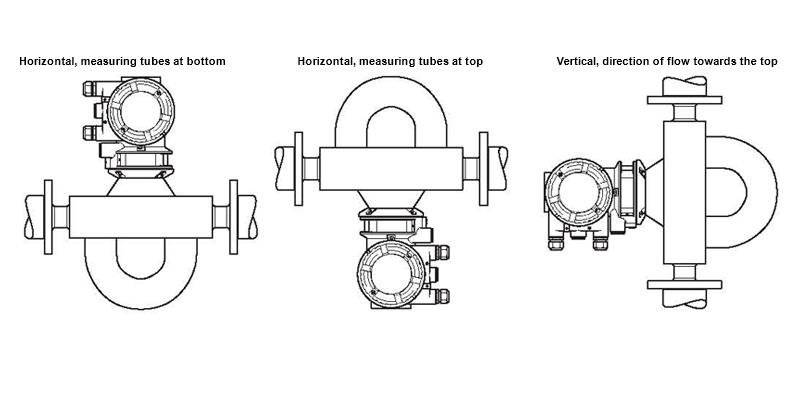
8. Location and position of installation